What Is an SMD DIP Switch?
An SMD DIP switch (Surface Mount Device Dual In-line Package) is a manual electric switch designed for surface mounting directly onto printed circuit boards (PCBs). Unlike traditional through-hole switches, these compact components utilize reflow soldering compatibility to enable high-density circuit configurations, allowing engineers to manually set hardware addresses, operational modes, and testing parameters without requiring complex software interfaces.
What Is the Primary Function of an SMD DIP Switch?
The primary function of an SMD DIP switch is to provide a reliable, manual interface for configuring electronic circuits on high-density PCBs. They allow technicians to physically set binary codes (ON/OFF states) that a microcontroller reads to determine device behavior, such as frequency channels, device addresses, or testing modes, without needing power to maintain the setting.
The Mechanics of Manual Configuration
At its core, an SMD DIP switch is a bank of isolated electromechanical switches—typically ranging from 1 to 12 positions—housed in a single high-temperature thermoplastic block. Each individual switch (or "pole") usually operates on a simple Single Pole Single Throw (SPST) mechanism. When you slide the actuator to the "ON" position, a gold-plated wiper bridges two internal contacts, completing the circuit.
Because they are "SMD" components, they lack the long metal leads of their through-hole ancestors. Instead, they feature "gull-wing" or "J-lead" terminals designed to sit flat on solder pads. This makes them indispensable in modern, automated assembly lines where pick-and-place machines handle components at high speeds.
Engineer’s Note: In my experience, the tactile "click" of a high-quality SMD DIP switch is subtle but critical. Cheaper variants often feel "mushy," leaving you unsure if the circuit is truly closed. Always spec switches with a defined actuation force (typically 4-8N) to avoid configuration errors during field service.
How Do SMD DIP Switches Differ from Through-Hole Versions?
SMD DIP switches differ primarily in their mounting method and heat resistance. While through-hole switches rely on pins inserted into drilled holes for mechanical strength, SMD versions are soldered to surface pads, requiring higher-temperature materials like Glass-Filled PPS to withstand reflow ovens (up to 260°C). This makes SMD versions ideal for automated, high-volume manufacturing.
Space Efficiency and Manufacturing
The shift from Through-Hole Technology (THT) to Surface Mount Technology (SMT) is driven by the need for miniaturization.
- PCB Real Estate: SMD switches eliminate the need for drilling holes through all PCB layers, freeing up space on the reverse side of the board for other components.
- Assembly Speed: THT switches often require manual insertion or wave soldering. SMD switches come in tape-and-reel packaging, ready for high-speed automated placement.
- Profile: SMD variants are frequently "low-profile" (often under 2.5mm height), allowing them to fit inside slim enclosures where a standard DIP switch would be too bulky.
For a deeper dive into standard switching mechanisms, you can explore tact dip switch fundamentals.
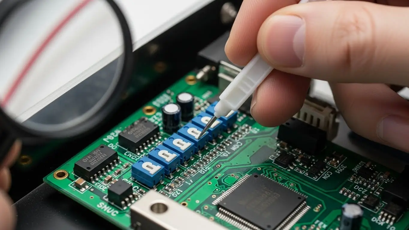
What Are the Key Types of SMD DIP Switches?
The three most common types of SMD DIP switches are Slide, Piano, and Rotary, each serving distinct accessibility needs. Slide switches are the standard for flat mounting; Piano switches offer side-access actuation for edge-mounted PCBs; and Rotary switches provide hexadecimal or binary coding in a compact footprint for complex addressing.
1. Slide Type (Standard & Low Profile)
This is the workhorse of the industry. The actuator slides horizontally.
- Best for: Motherboards and set-and-forget configurations.
- Pro Tip: Look for "flush" actuators if you plan to apply a tamper-proof sticker over the switch bank.
2. Piano Type (Side-Actuated)
Named for their resemblance to piano keys, the actuators move up and down.
- Best for: PCBs stacked vertically in a rack (like server blades) where you can only access the edge of the board.
- Comparison: Unlike a low profile tact switch used for user input, piano DIPs are strictly for configuration.
3. Rotary DIP Switches
Instead of a row of levers, this uses a rotating dial that internally bridges contacts to output a BCD (Binary Coded Decimal) or Hexadecimal code.
- Best for: Setting device IDs in RS-485 networks where you need to select a number from 0-15 quickly using a small screwdriver.
How Do You Solder SMD DIP Switches Correctly?
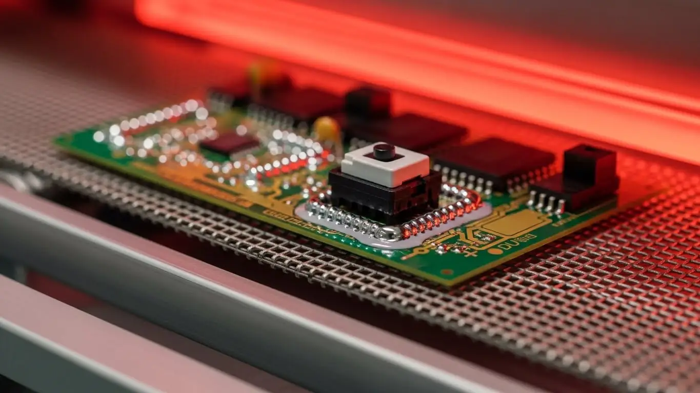
To solder SMD DIP switches correctly, you must strictly adhere to a reflow profile that peaks between 250°C and 260°C for no more than 10 seconds. Because the housing is plastic, exceeding these limits can warp the body, causing the internal contacts to misalign or the actuator to seize.
Reflow Profile & Material constraints
The "gotcha" with SMD DIP switches is the housing material. Unlike standard switches made of Nylon or ABS, high-quality SMD switches use Glass-Filled PPS (Polyphenylene Sulfide) or LCP (Liquid Crystal Polymer). These materials have a deflection temperature of over 260°C.
Critical Reflow Stages:
- Pre-Heat: 150°C to 200°C for 60-120 seconds. This activates the flux without shocking the component.
- Reflow Zone: Ramp up to peak (260°C max). Time above liquidus (TAL) should be kept under 60 seconds.
- Cool Down: Gradual cooling to prevent thermal shock cracking the solder joints.
Warning: Never attempt to wave solder an SMD switch unless it is specifically rated for it and you are using a "top-side" masking process. The thermal wave will almost certainly melt a standard SMD actuator.
Why Is Sealing Critical for Washable SMD DIP Switches?
Sealing is critical because standard flux washing processes can wick contaminants into the switch housing, coating the contacts and causing open circuits. "Washable" SMD DIP switches feature a polyimide tape seal over the actuators or an internal rubber O-ring/epoxy seal to prevent solvent ingress during cleaning.
The "Tape Seal" Necessity
After reflow soldering, PCBs are often washed to remove corrosive flux residues.
- The Failure Mode: If you wash an unsealed DIP switch, the dissolved flux washes inside the switch. When the solvent evaporates, it leaves behind a sticky, insulating layer of flux on the gold contacts. This results in intermittent connections—often misdiagnosed as a "bad switch."
- The Solution: Always spec switches with top tape seals if your assembly line uses an aqueous wash. You must manually peel this tape off after the washing and drying process is complete.
For environments requiring robust protection, understanding sealed tact switches and waterproof tactile switches can provide further insight into IP-rated sealing technologies.
What Is "Contact Bounce" and Does It Affect DIP Switches?
Contact bounce is the transient oscillation of switch contacts that occurs during actuation, typically lasting milliseconds. While critical for momentary switches, it rarely affects DIP switches since they are static configuration devices; however, if a DIP switch is read dynamically by a microcontroller, software debouncing is required to prevent false triggering.
Addressing "Chatter" in Static Switches
You might be familiar with "chatter" in machining or "bounce" in how a tact switch works, where the signal fluctuates rapidly before settling.
- Static Use: Most DIP switches are read only once at startup (boot time). In this case, bounce is irrelevant.
- Dynamic Use: If your DIP switch changes "on the fly" while the device is running, your firmware must include a debounce routine (usually a 20ms delay) to ensure the signal is stable before acting on it.
What Are the Common Applications in Modern Electronics?
Common applications include setting RF frequencies in garage door openers, configuring DMX addresses in stage lighting, and defining master/slave modes in industrial hard drives. Despite the rise of software configuration, SMD DIP switches remain the industry standard for "hard" settings that must survive power cycles and software crashes.
Industry-Specific Use Cases
| Industry | Application | Why SMD DIP? |
| Industrial Automation | Setting Modbus Addresses | Reliability; visual confirmation of address without power. |
| Consumer Electronics | Universal Remote Controls | Low cost; allows users to match frequency with receiver. |
| Security Systems | Zone Configuration | Hard-coded security that cannot be hacked via software. |
| Telecommunications | Line Impedance Matching | Precision control over signal paths on line cards. |
If your application involves user interaction rather than configuration, you might be looking for how illuminated tact switches work, which offer visual feedback for active switching.
Troubleshooting Checklist for SMD DIP Switches
If you are experiencing failures with SMD DIP switches, run through this diagnostic checklist based on common field issues.
- Issue: Switch reads "Open" even when set to "ON".
- Cause: Flux contamination. Did you wash an unsealed switch?
- Fix: Replace the switch. Contact cleaners rarely work effectively on sealed SMD units. Use tape-sealed versions for future builds.
- Issue: Plastic actuator is deformed or stuck.
- Cause: Reflow temperature too high.
- Fix: Check your oven profile. Ensure the peak temp does not exceed 260°C and verify the switch body material is PPS or LCP, not Nylon.
- Issue: Solder joints are cracking (Intermittent signal).
- Cause: Thermal mismatch or board flexing.
- Fix: Ensure the PCB pads are designed with the correct "toe and heel" length to allow for minor thermal expansion.
- Issue: Actuator breaks during setting.
- Cause: Using incorrect tools.
- Fix: Never use a pencil (graphite is conductive and can cause shorts) or a sharp metal scribe. Use a plastic adjustment tool or a ballpoint pen with the ink retracted.
FAQ
Yes, but it requires skill. Use a fine-tip soldering iron and thin solder wire (0.5mm). Tack one pin first to align the switch, then solder the rest. Do not keep the iron on a pin for more than 3 seconds to avoid melting the plastic housing.
The standard pitch is 2.54mm (0.100 inches), which matches standard breadboard spacing. However, "Half-Pitch" SMD DIP switches at 1.27mm (0.050 inches) are becoming increasingly popular for ultra-compact devices.
Generally, no. While "washable" switches have a tape seal for cleaning, they are not IP67 rated for continuous immersion. For true water resistance during operation, you need specialized sealed switches or conformal coating (applied carefully to avoid the switch actuator).
Gold is highly resistant to oxidation and corrosion. Since DIP switches are often set once and left for years, gold ensures that the contact resistance remains low (typically <50mΩ) even after long periods of inactivity in harsh environments.