


Through-Hole Tact Switch Guide: When to Use THT Switches
Not every tactile switch belongs on the surface of a PCB. In applications where mechanical stress, vibration, or repeated heavy actuation is involved, a through-hole tact switch is often the right tool — and choosing the wrong mounting type can lead to premature solder joint failure, unreliable button response, or costly redesigns.
This guide explains exactly what a through-hole tact switch is, how it works, when it outperforms its SMD counterpart, and what specifications and design factors to evaluate before you place your order or finalize your PCB layout.
What Is a Through-Hole Tact Switch?
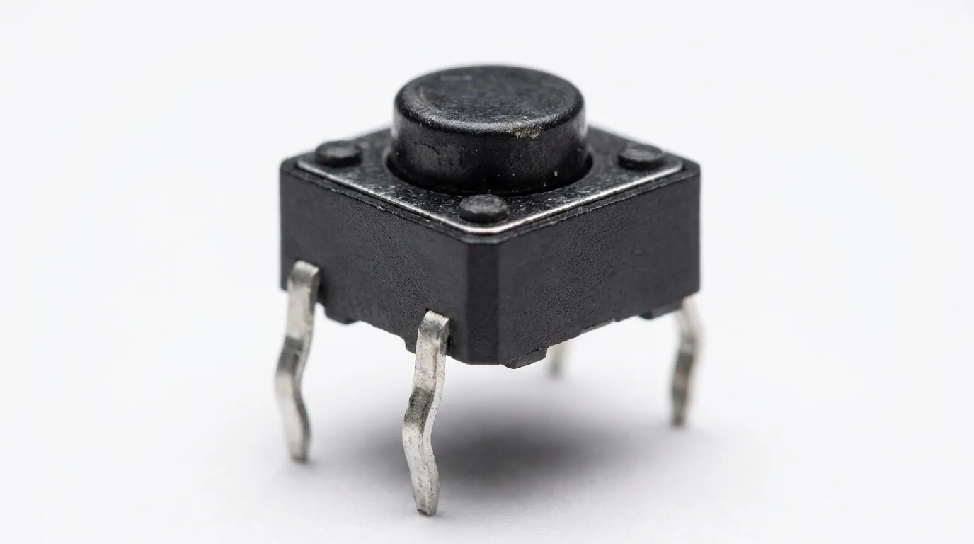
A through-hole tact switch (also called a THT tact switch or DIP tact switch) is a momentary push-button switch with metal leads that pass through drilled holes in a PCB and are soldered on the reverse side of the board.
The "through-hole" part refers to the mounting method, not the switch mechanism. The switch itself operates as a standard momentary contact — press the actuator, the circuit closes; release it, the circuit opens and the spring returns the actuator to its resting position. What sets THT apart is how the component anchors to the board. Because the leads physically pass through the PCB and are soldered on the underside, the mechanical bond between switch and board is significantly stronger than a surface-mounted pad. This makes through-hole tact switches the preferred choice in environments where the switch will face lateral force, vibration, or physical handling.
If you are new to tact switches generally and want to understand all available types — including sealed, illuminated, and SMD variants — the complete tact switch guide covers the full product family in detail.
How a Through-Hole Tact Switch Works
The internal mechanism of a THT tact switch is the same snap-action, metal dome design used across most tactile switches. When you press the actuator cap, it depresses a metal dome or spring contact beneath it. At a defined pressure threshold — the actuation force — the dome collapses and bridges the circuit between the two contact points. This closure is what registers the input signal. When pressure is released, the dome springs back and the circuit opens.
What makes the through-hole design functionally distinct is the lead structure. THT switches have rigid metal leads — typically 0.5mm to 0.6mm in diameter — that extend downward from the switch body and insert into drilled PCB holes. After placement, these leads are soldered, either through wave soldering in a production environment or by hand for prototyping. The resulting solder joint wraps around the lead inside the plated through-hole, creating a strong mechanical and electrical connection on three surfaces rather than just the flat pad adhesion of an SMD solder joint.
Pin Configuration: 2-Pin vs. 4-Pin
Most through-hole tact switches use a 4-pin configuration. In a standard 4-pin layout, the pins are arranged in two pairs: pins 1 and 2 are internally connected, and pins 3 and 4 are internally connected. When the switch is pressed, it bridges the two pairs and completes the circuit. The redundant pin pairs serve a dual purpose — they provide electrical redundancy, and more importantly, they give the switch physical stability by creating four anchoring points on the PCB rather than two.
Two-pin versions also exist and are used in simpler circuits where PCB space is limited and mechanical load is low. For most applications involving any form of physical handling, the 4-pin configuration is the more reliable choice.
Through-Hole vs. SMD Tact Switch: Key Differences
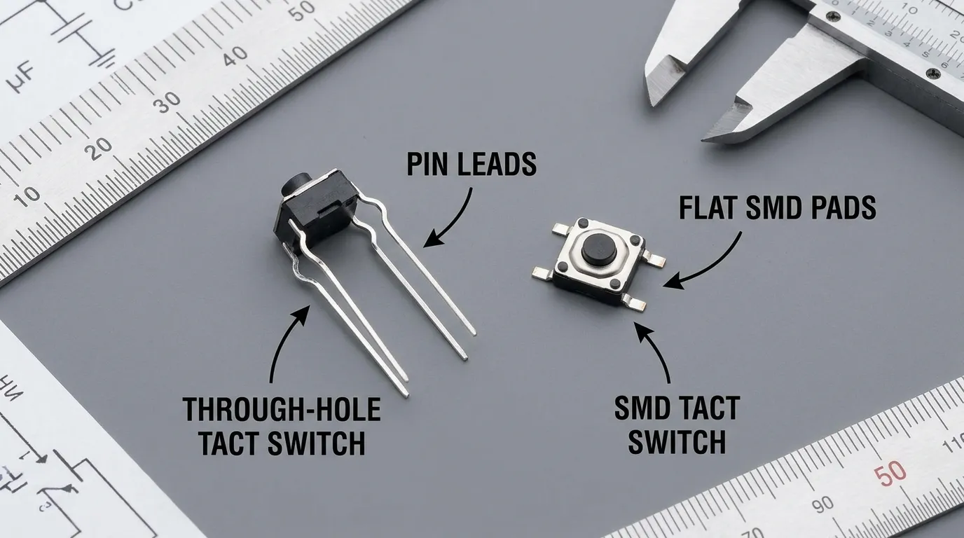
The most common decision point engineers face is whether to specify a THT or SMD tact switch for a given design. Both types use the same actuation mechanism — the difference is entirely in mounting, assembly process, solder joint mechanics, and the resulting mechanical properties.
| Feature | Through-Hole (THT) | Surface Mount (SMD) |
|---|---|---|
| Mounting method | Leads through PCB holes, soldered on reverse | Pads soldered directly to PCB surface |
| Solder joint strength | High — 3-surface bond inside plated hole | Moderate — flat pad adhesion only |
| Mechanical shear resistance | Excellent | Limited |
| Assembly method | Wave soldering or hand soldering | Reflow soldering |
| Breadboard compatible | Yes — standard 2.54mm pitch | No |
| Board space usage | Larger footprint + requires drilling | Compact footprint, no drilling required |
| Rework and replacement | Straightforward — desoldering and reinsertion | Requires hot air or reflow station |
| Cost at volume | Slightly higher due to drilling and wave solder | Lower for automated SMT lines |
| Best for | Industrial, automotive, prototyping, heavy-use | Consumer electronics, compact devices |
The main difference is in mechanical holding strength. An SMD solder joint relies on the adhesion between a flat pad and the PCB surface. A THT joint wraps around a lead inside a plated barrel — it resists pulling, pushing, and lateral shear forces far more effectively. In applications where a user presses a button with any lateral angle, or where the board experiences vibration, this difference is significant.
For a full comparison of SMD tactile switch types and their applications, the SMD tact switch guide covers the surface-mount side in detail. If you need clarity on the terminology difference between SMT and SMD, this explanation of the difference between SMT and SMD switches addresses that specifically.
When Should You Use a Through-Hole Tact Switch?
This is the core question. Through-hole tact switches are not simply an older technology that SMD is replacing — they are the correct technical choice in specific, well-defined scenarios. Choosing THT when it is the right fit will result in a more reliable product. Choosing SMD when THT is needed will result in field failures.
Industrial and Automotive Applications
Control panels for industrial machinery, process automation equipment, and vehicle dashboards expose switches to mechanical stress that SMD solder joints cannot reliably handle. An operator pressing a panel-mounted control button often applies force at a slight angle. Over thousands of actuation cycles, the lateral shear force on an SMD solder joint will eventually cause pad lift or joint cracking. A THT lead, soldered through the board, absorbs that lateral force without degrading. For this reason, through-hole tact switches are the standard choice in industrial control panels, automotive interior switches, and ruggedized instrumentation where long-term mechanical reliability is required.
Prototyping, Development, and Educational Use
Through-hole tact switches are inherently breadboard-compatible because their 2.54mm lead pitch matches the standard breadboard hole spacing. For engineers and developers who need to build and iterate a circuit quickly — without committing to a PCB layout — THT tact switches can be inserted directly into a breadboard or perfboard. SMD switches cannot. For Arduino-based projects, Raspberry Pi peripherals, and electronics education kits, THT switches are the practical and accessible choice.
Professional Audio Equipment and Test Instruments
High-cycle applications — professional mixing consoles, signal testers, laboratory instruments, and measurement devices — demand switches that will perform reliably across hundreds of thousands or millions of actuations. These environments also typically favor field serviceability: when a switch does eventually wear out after years of use, a THT switch can be desoldered and replaced by a technician without specialized equipment. The repairability advantage of through-hole mounting is a genuine long-term cost consideration for equipment that is expected to be serviced rather than discarded.
When THT Is Not the Right Choice
THT is not the right choice when board space is at a premium, when the entire assembly is running through a fully automated SMT reflow line with no wave solder stage, or when the device is a compact consumer product with no significant mechanical stress on the switch. In those cases, an SMD tact switch delivers better space efficiency and production economics without sacrificing reliability.
Through-Hole Tact Switch Specifications: What to Check
Before selecting a through-hole tact switch, verify these key specifications against your application requirements. Using a switch outside its rated range will shorten its service life and may introduce intermittent contact failures.
| Specification | Typical Range | What to Consider |
|---|---|---|
| Body size | 6×6mm, 12×12mm | Must fit PCB footprint and panel cutout |
| Actuator height | 3mm to 13mm+ | Match to panel depth and required travel feel |
| Actuation force | 100gf – 260gf | Lower for frequent user-facing controls; higher for deliberate-actuation applications |
| Rated voltage | 12V DC (typical) | Confirm compatibility with your circuit voltage |
| Rated current | 50mA (typical) | Verify signal load requirements |
| Contact resistance | ≤100mΩ | Lower is better for signal integrity |
| Operating temperature | -20°C to +70°C (standard) | Industrial applications may require extended range |
| Operating life | 100,000 – 2,000,000 cycles | High-cycle applications need long-life rated switches |
| Lead pitch | 2.54mm (standard) | Confirms breadboard and standard PCB footprint compatibility |
| Contact plating | Gold or silver | Gold offers better corrosion resistance in low-voltage signal applications |
Actuation force is one of the most underspecified parameters. A 100gf switch feels light and responsive — suitable for a frequently used user interface button. A 260gf switch requires deliberate force — appropriate for an emergency stop or a control that should not be accidentally triggered. Getting this wrong creates poor user experience even when everything else is technically correct.
Operating life matters more than many buyers initially realize. A switch rated for 100,000 cycles will reach end-of-life in roughly 55 days if it is actuated once every 47 seconds throughout a full working day. High-frequency applications demand long-life versions rated at 500,000 cycles or higher.
PCB Design Considerations for THT Tact Switches
PCB layout for through-hole components requires more upfront planning than SMD placement, but it is straightforward if the key dimensions are specified correctly from the start.
Drill hole diameter should be approximately 0.1mm to 0.15mm larger than the lead diameter to allow for clean insertion while still ensuring a good solder fill. For a standard 0.5mm lead, a 0.65mm drill hole is typical. Too tight and the switch will not insert cleanly; too loose and the solder joint will have insufficient contact area.
Annular ring — the pad of copper surrounding the drill hole — should be at least 0.25mm to 0.3mm wide to ensure reliable soldering and to withstand multiple thermal cycles. Undersized annular rings are one of the most common causes of pad separation on through-hole components.
Lead pitch for standard 6×6mm through-hole tact switches is 2.54mm between adjacent leads, with a 4.5mm diagonal pitch for 4-pin versions. Confirm the exact footprint of your selected switch before finalizing the PCB layout, as minor dimensional variations exist between manufacturers.
Component clearance matters because THT switches sit above the PCB surface on the component side. Ensure there is sufficient clearance from adjacent components, particularly tall capacitors or connectors, so the actuator can be pressed freely without interference.
How to Solder a Through-Hole Tact Switch
For production environments, through-hole tact switches are typically soldered using wave soldering. The populated PCB passes over a wave of molten solder, which wicks into the plated through-holes and forms solid joints on the underside of the board. This process is fast, consistent, and suitable for high-volume assembly. If your board is primarily SMT with only a few through-hole components, a selective soldering machine or solder pallet can isolate the THT components during the wave solder pass.
For prototyping or low-volume work, hand soldering is straightforward. Insert the switch leads through the PCB holes, ensure the switch body sits flat against the board, and apply solder at the junction of each lead and pad on the underside. Use a temperature-controlled iron set to 320°C–360°C, apply solder quickly (2–3 seconds per joint), and avoid applying heat for extended periods, which can damage the contact mechanism inside the switch.
To desolder and replace a failed THT switch, use a solder sucker or desoldering braid to remove solder from each lead hole, then extract the switch cleanly. Through-hole desoldering is more time-consuming than SMD rework but requires only basic equipment — no hot air station needed.
How to Choose the Right THT Tact Switch
Use this checklist when specifying a through-hole tact switch for a new design or a replacement component.
Application environment:
- Will the switch face lateral force, vibration, or physical handling? → THT is confirmed correct
- Is the operating temperature outside -20°C to +70°C? → Specify an extended-temperature version
- Is moisture or dust exposure possible? → Specify a sealed/waterproof THT variant
Actuation feel and ergonomics:
- Frequent, light user interaction → specify 100–150gf actuation force
- Deliberate or safety-related actuation → specify 200–260gf
- Panel-mounted with specific depth → confirm actuator height matches panel thickness
Electrical requirements:
- Signal circuit (logic level) → standard 12V DC / 50mA rating is sufficient
- Verify contact resistance ≤100mΩ for signal integrity in low-voltage circuits
- Gold-plated contacts are preferred for low-voltage, low-current applications where contact oxidation is a concern
Lifecycle requirements:
- Standard low-frequency prototype use → 100,000 cycles is adequate
- Professional equipment or industrial controls → specify 500,000 cycles minimum
- High-cycle or mission-critical application → specify long-life versions rated at 1–2 million cycles
PCB and assembly constraints:
- Confirm body size (6×6mm or 12×12mm) against your PCB footprint
- Confirm your assembly process supports wave or hand soldering
- Confirm lead pitch (2.54mm standard) matches your drilled footprint
For a broader comparison across all tact switch types — including waterproof and illuminated options — review the full tact switch selection guide to ensure through-hole is the right category before finalizing your specification.
Common Mistakes When Using THT Tact Switches
Using the wrong actuator height. Actuator height must match the panel cutout depth. A switch that sits too deep below a panel face will require excessive force to operate. One that protrudes too far will be prone to accidental actuation. Measure your panel thickness and select accordingly.
Undersizing the drill hole. A drill hole that is too tight prevents full lead insertion, which results in a cold solder joint with insufficient fill. This is a latent defect — it may pass initial testing but fail under thermal cycling or vibration.
Ignoring the lifecycle rating for the application. Engineers frequently specify the cheapest available switch without checking rated life cycles. For a button that will be pressed 100 times a day, a 100,000-cycle switch will last approximately 3 years. For industrial equipment expected to run for a decade, that is inadequate.
Applying lateral force to leads during soldering. Bending or stressing the leads while they are still hot causes micro-fractures in the solder joint. Secure the component before soldering and allow each joint to cool completely before moving the board.
Overlooking contact plating for low-voltage circuits. Silver contacts are cost-effective and perform well at standard voltages. In low-voltage, low-current signal applications (under 1V, under 1mA), silver oxide buildup can cause intermittent contact failures. Gold plating prevents this and should be specified for sensitive logic circuits.
Specifying THT on a reflow-only assembly line. If your board has THT components but your contract manufacturer runs a reflow-only process, your THT switches will not be soldered automatically. Confirm your assembly process supports THT before finalizing the BOM.
Related Guides
If you are evaluating tact switch options across mounting types, the complete guide to tact switches covers all available switch families — including SMD, waterproof, and illuminated variants — in a single reference.
For applications where board space is constrained and mechanical load is low, the SMD tact switch guide provides a parallel deep dive into surface-mount tactile options, covering the same specification and selection factors from an SMD perspective.
If you have encountered conflicting use of "SMT" and "SMD" in supplier datasheets or industry documentation, the SMT vs. SMD tact switch explanation clarifies the terminology distinction clearly.
Frequently Asked Questions
What is a through-hole tact switch?
A through-hole tact switch is a momentary push-button switch with metal leads that pass through drilled holes in a PCB and are soldered on the underside. The through-hole mounting method creates a stronger mechanical bond than surface-mount alternatives, making it the preferred choice for applications involving mechanical stress, vibration, or physical handling.
What is the difference between a THT and SMD tact switch?
The key difference is the mounting method and resulting mechanical strength. THT switches have leads soldered through PCB holes, giving them excellent resistance to lateral shear forces. SMD switches have pads soldered to the PCB surface, making them more compact but less mechanically robust. THT switches are also breadboard-compatible and hand-solderable; SMD switches are not.
When should I use a through-hole tact switch instead of SMD?
Choose THT when the application involves mechanical stress, vibration, frequent heavy actuation, hand-soldered assembly, breadboard prototyping, or a requirement for field serviceability. Choose SMD when board space is tight, the assembly is fully automated through a reflow process, and mechanical load on the switch is minimal.
What are the standard sizes for through-hole tact switches?
The most common body sizes are 6×6mm and 12×12mm. Actuator heights typically range from 3mm to over 13mm. Lead pitch is standardized at 2.54mm, making THT switches directly compatible with standard breadboards and common PCB footprint libraries.
What actuation force should I specify?
For user-facing buttons that are pressed frequently, 100–160gf provides a light, responsive feel. For controls that require deliberate actuation to prevent accidental triggering, 200–260gf is more appropriate. Confirm the required force with a physical sample before finalizing your design.
Can I solder a through-hole tact switch by hand?
Yes. THT switches are straightforward to hand solder using a standard temperature-controlled iron. This makes them the practical choice for prototyping, low-volume production, and field repair situations where wave soldering equipment is not available.
What operating life should I specify?
For standard low-frequency applications, 100,000 cycles is a common baseline. For professional equipment or industrial controls, specify 500,000 cycles or higher. Long-life THT switches rated at 1–2 million cycles are available for high-frequency or mission-critical applications.
Are waterproof through-hole tact switches available?
Yes. Sealed THT tact switches with IP65 or higher ratings are available for applications requiring protection against dust and moisture ingress, including outdoor control panels, industrial enclosures, and marine environments.
Conclusion
Through-hole tact switches are not the universal default they once were, but they remain the definitive choice in applications where mechanical reliability, repairability, and breadboard compatibility matter. The decision to use THT over SMD should be driven by the physical demands of your application — not by habit or component availability.
If your design involves any combination of physical handling, vibration, high-cycle actuation, or hand assembly, a THT tact switch will outperform a surface-mount equivalent over the product lifetime. Specify the correct body size, actuator height, actuation force, and lifecycle rating against your application requirements, and confirm your PCB layout accounts for correct drill hole sizing and adequate annular rings.
For applications where SMD is more appropriate, or when you need to compare options across the full tact switch family before making a final specification decision, the complete tact switch guide is the right next step.