Right Angle Tact Switch Guide for Side-Actuated PCB Designs
Your PCB layout is finalized, your enclosure design is locked in — and then you realize the button must be accessed from the side of the device, not the top. A standard upward-facing tact switch won't work. The actuator points the wrong direction.
This is exactly the problem that right angle tact switches solve. They are a specialized variant of the momentary push-button switch, built specifically for PCB designs where side actuation, front-panel access, or edge-mounted button placement is required.
This guide covers everything a PCB designer or hardware engineer needs to know before selecting and integrating a right angle tact switch — from how they work and how they mount, to key specifications, common mistakes, and a practical selection framework.
What Is a Right Angle Tact Switch?
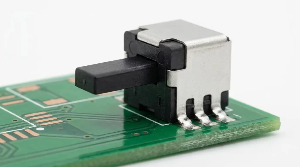
A right angle tact switch is a momentary push-button switch where the actuator exits the switch body horizontally, running parallel to the PCB surface, rather than pointing upward. When you press the switch, you are applying force from the side — not from the top.
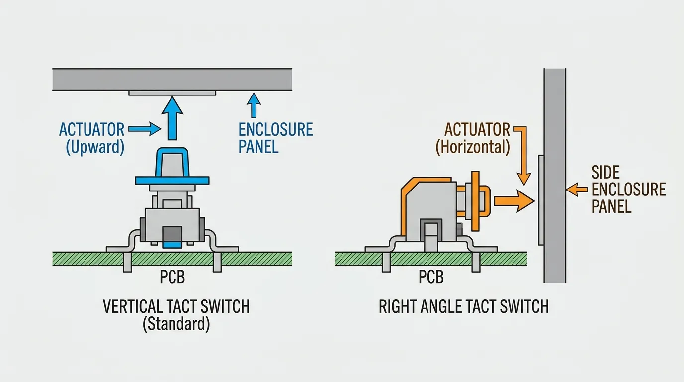
The term "right angle" refers to the 90° orientation between the actuator axis and the PCB mounting plane. In a standard vertical tact switch, the actuator points perpendicular to the board (upward). In a right angle switch, that same actuator has been rotated 90°, so it now points outward along the edge of the board.
This small geometric change solves a major design constraint: it allows the switch to be mounted flat on the PCB while still being accessible from a side wall, front panel, or enclosure edge. If you need to understand how right angle switches fit within the full category of momentary push-button switches, the complete guide to tact switches from Hanxia covers all available types in detail.
How a Right Angle Tact Switch Works
Internally, a right angle tact switch uses the same operating mechanism as any standard tact switch. When the actuator is pressed, it collapses a metal dome contact, which briefly completes the electrical circuit. When force is released, the dome springs back and the circuit opens. The result is a momentary ON contact with crisp tactile feedback.
What changes is the geometry of actuation. In a vertical tact switch, pressing downward collapses the dome. In a right angle switch, pressing horizontally along the PCB surface achieves the same result — the switch body is simply rotated so the dome collapses in response to lateral force.
Because of this orientation, the critical measurement for a right angle switch is actuator length, not actuator height. Actuator length is defined as the distance between the actuating surface and a reference point on the switch body, measured along the horizontal axis. This dimension determines how far the button protrudes through your enclosure panel, and it must be calculated carefully during the design phase.
Right Angle vs. Standard Vertical Tact Switch
Many engineers default to a vertical tact switch and only revisit the decision when an enclosure constraint forces a rethink. Understanding the difference from the start prevents costly PCB revisions.
| Feature | Right Angle Tact Switch | Standard Vertical Tact Switch |
|---|---|---|
| Actuation direction | Horizontal (side-facing) | Vertical (top-facing) |
| Actuator exits toward | PCB edge / enclosure side panel | Top of PCB / enclosure top panel |
| Critical measurement | Actuator length | Actuator height |
| PCB space usage | Longer horizontal footprint | Compact vertical profile |
| Best for | Front panel or side-access enclosures | Top-access button layouts |
| Enclosure integration | Front panel or side wall cutout | Top lid cutout |
| Component height clearance | Lower vertical profile needed | Requires overhead clearance |
| Common applications | Wearables, remote controls, handheld tools | Keyboards, PCB test buttons, remote controls |
The main difference is the direction the button faces relative to your board. If your enclosure requires a button on its side or front face — and your PCB sits horizontally inside that enclosure — a right angle switch is the correct choice. A standard vertical switch in the same scenario would require either a mechanical plunger extension or a complete redesign of the board orientation.
SMT vs. THT Right Angle Tact Switches
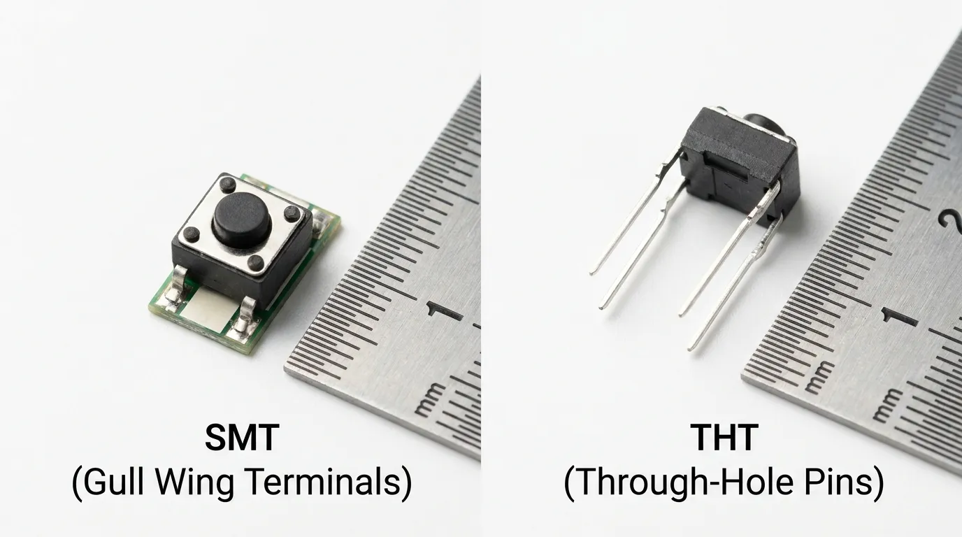
Right angle tact switches are available in both surface mount (SMT) and through-hole (THT) configurations. The choice between them affects your assembly process, mechanical durability, and PCB design approach.
| Attribute | SMT Right Angle | THT Right Angle |
|---|---|---|
| Terminal type | Gull wing (surface pads) | Through-hole pins |
| Soldering method | Reflow soldering | Wave or hand soldering |
| PCB profile | Lower, more compact | Slightly taller, more robust |
| Mechanical anchor strength | Moderate (pad-dependent) | High (pins through board) |
| Resistance to lateral force | Lower — pad stress risk | Higher — pins provide mechanical lock |
| Assembly suitability | Automated pick-and-place | Manual or wave soldering lines |
| Packaging | Tape-and-reel (high-volume) | Bulk packaging |
| Typical body outline | 2.00×2.80mm to 6.00×5.40mm | 6.00×6.00mm to 12.00×12.00mm |
| Best for | Compact, high-volume products | High-use, mechanically stressed applications |
SMT right angle switches are the right choice when your product uses automated PCB assembly, needs a compact footprint, and is produced in high volume. They are standard in wearables, key fobs, remote controls, and slim consumer electronics where board space is at a premium.
THT right angle switches provide a stronger mechanical connection because the pins pass through the PCB and are soldered on the underside. If your application involves frequent, forceful pressing — or the switch will be exposed to mechanical stress during handling — THT mounting provides significantly better long-term reliability.
One important design consideration: SMT right angle switches are vulnerable to pad separation if lateral force is applied directly to the actuator. The solder joints carry both the electrical and mechanical load. To reduce this risk, choose SMT variants with a mounting boss (an extra mechanical anchor point), ensure the land pattern is correctly sized for the gull wing termination, and design the enclosure so the panel cutout absorbs some of the button force rather than transferring all of it to the solder joints.
Key Specifications to Understand
Selecting the wrong specification is a more common mistake than selecting the wrong switch type. These are the parameters that actually determine whether a right angle tact switch works in your design.
| Specification | What It Means | Typical Range | Design Consideration |
|---|---|---|---|
| Actuator length | Horizontal distance from actuating surface to switch body reference | 0.65mm to 11.2mm+ | Must equal enclosure panel thickness + desired button protrusion |
| Operating force | Force required to actuate the switch | 100gf, 160gf, 260gf, 300gf+ | Lower = easier press; higher = more deliberate actuation required |
| Switch body outline | Physical footprint dimensions | 2.00×2.80mm to 12.00×12.00mm | Determines PCB area required and clearance needs |
| Electrical lifecycle | Rated actuation cycles before contact degradation | 50,000 to 2,000,000+ | Match to expected usage frequency over product lifetime |
| Contact material | Gold or silver plating on internal contacts | Gold or silver | Gold: better for low-voltage/low-current, higher reliability; Silver: suitable for standard voltage ranges |
| IP / sealing rating | Degree of protection against dust and moisture | Standard, process sealed, IP67 | IP67 required for outdoor, washdown, or humid environments |
| Operating temperature | Temperature range for reliable operation | −40°C to +85°C (typical) | Critical for automotive, industrial, or outdoor applications |
| RoHS compliance | Restriction of hazardous substances conformity | RoHS compliant | Required for CE-marked or EU-market products |
On operating force: 100gf feels light and responsive — appropriate for frequent-use buttons on consumer devices. 160gf is the most common choice and offers standard tactile feedback similar to a laptop keyboard key. 260gf and above require deliberate intent to press, which reduces accidental actuation in industrial or safety-critical applications.
On contact material: Gold contacts are recommended when the switch operates at low voltages (below 12V DC) or low current levels (below 10mA), where silver contacts may tarnish and increase contact resistance over time. For standard 5V or 12V switching applications with normal current levels, silver is adequate and more cost-effective.
PCB Layout and Footprint Design for Right Angle Mounting
Getting the PCB footprint right for a right angle switch requires more attention than a standard vertical switch. The switch body sits flush on the board, but the actuator must align precisely with a cutout in the enclosure panel. Any misalignment — in footprint orientation, board edge placement, or actuator length selection — results in a button that is misaligned, recessed too deep, or unable to reach the panel at all.
Footprint orientation is the first thing to confirm. The footprint must be placed so the actuator faces the correct PCB edge. This sounds obvious, but it is one of the most frequent placement errors in early prototypes. Mark the switch orientation clearly on the silkscreen layer, especially if your assembly team places components manually.
Board edge clearance determines whether the actuator can actually reach the enclosure wall. The switch body needs to be placed close enough to the PCB edge so that the actuator extends beyond the board outline and into the enclosure panel cutout. The exact placement depends on the switch body dimensions and your chosen actuator length — always verify this against your enclosure CAD model before fabricating boards.
Enclosure panel cutout sizing must match the actuator's cross-section at the protrusion point, with enough tolerance for smooth insertion without slop. A cutout that is too tight will bind the actuator; one that is too loose will allow lateral movement and premature pad stress on SMT variants.
For SMT right angle switches, the land pattern must be designed to the manufacturer's recommended dimensions for the specific gull wing termination. Under-sized pads reduce mechanical strength significantly. If the product will see regular physical handling or shipping vibration, select a switch model with an integrated mounting boss — a small mechanical pin that inserts into a PCB hole to provide additional structural support independent of the solder joints.
Component clearance around the switch body is easy to underestimate. Right angle switches extend horizontally, and depending on the body size (particularly 12×12mm THT variants), they can conflict with adjacent components if PCB density is high. Review clearances on all four sides of the switch body, not just around the actuator.
Where Right Angle Tact Switches Are Used
Right angle tact switches are used wherever a product's physical form factor requires button access from the side or front, while the PCB sits horizontally inside the enclosure.
| Application | Why Right Angle Switch Is Required | Typical Spec Requirement |
|---|---|---|
| Smartwatch / wearable fitness tracker | Side crown or button in slim wrist-worn enclosure | Ultra-compact SMT, 2×2.8mm or smaller, short actuator length |
| Remote control (TV, audio, automotive) | Side-facing function buttons on handheld device | SMT or THT, 160gf, standard lifecycle |
| Key fob / proximity access device | Edge-mounted press button in thin molded housing | SMT, very compact outline, process sealed preferred |
| Handheld diagnostic tool | Front panel button accessible during single-hand operation | THT, 160–260gf, sealed/IP-rated for field use |
| Laptop / tablet side buttons | Volume or function buttons on device edge | SMT, compact, tape-and-reel packaging |
| Portable audio device | Side transport controls on compact player or recorder | SMT, low-profile, 100–160gf |
| Industrial front-panel control enclosure | Operator-accessible buttons on control box face | THT, 260gf+, IP67 sealed, gold contact, wide temperature range |
| Wearable camera / sports tracker | Rugged side button on action camera housing | Sealed, high lifecycle, reliable under vibration |
The common thread across all these applications is the same physical constraint: the PCB is horizontal, the enclosure is sealed, and user access is from the side. A right angle switch is not an alternative — it is the only correct switch type for this geometry.
How to Select the Right Right Angle Tact Switch
Use this seven-step framework to narrow your selection before contacting a supplier. Working through these questions in sequence will eliminate most of the wrong options before you compare specific models.
Step 1 — Confirm side actuation is required. Verify that your enclosure design physically requires horizontal button access. If the button can face upward without any mechanical adaptor, a standard vertical switch may be simpler. If the button must exit through a side or front panel, proceed with a right angle selection.
Step 2 — Choose SMT or THT based on your assembly process and mechanical requirements. If your PCB goes through an automated reflow oven and your product will not be subjected to heavy mechanical stress on the switch, SMT is the right choice. If you are hand-soldering or wave-soldering, or if the switch will be pressed frequently and forcefully, use THT.
Step 3 — Calculate the required actuator length. Measure your enclosure panel thickness and determine how far you want the button to protrude beyond the panel surface. The actuator length must equal at least the sum of these two dimensions plus the distance from the PCB edge to the switch body reference point. Get this wrong and your button will either be flush with the panel (unresponsive feel) or it won't reach the cutout at all.
Step 4 — Select operating force based on user experience. For consumer devices used frequently with light touch, 100gf–160gf is appropriate. For industrial controls or applications where accidental actuation is a risk, 260gf or higher is recommended.
Step 5 — Match the lifecycle rating to expected usage. A switch rated at 50,000 cycles in a product used five times per day will last approximately 27 years. In a high-use industrial application with 100 activations per day, that same switch reaches end-of-life in under two years. Select the lifecycle rating that corresponds to realistic product usage over its expected service life.
Step 6 — Decide on IP sealing. If the product will be exposed to water, humidity, cleaning agents, or dust in service — choose a sealed or IP67-rated right angle switch. If the switch is fully enclosed inside a sealed product enclosure, a standard (non-sealed) switch is typically sufficient.
Step 7 — Select contact material. Use gold contacts for low-voltage signal-level switching (below 12V, below 10mA). Use silver contacts for standard 5V–24V DC switching at normal current levels where cost efficiency matters.
For a broader comparison of all tact switch types and mounting options available from Hanxia, refer to the full overview of Hanxia tact switches before finalizing your specification.
Common Mistakes in Right Angle Tact Switch PCB Design
These mistakes appear repeatedly in both prototype and production PCB designs. Avoiding them before your first board spin saves both time and cost.
| Mistake | Root Cause | How to Avoid It |
|---|---|---|
| Incorrect actuator length | Not accounting for panel thickness + protrusion distance during design | Calculate actuator length from your enclosure CAD model before selecting a switch series |
| Wrong footprint orientation | Switch placed with actuator facing the wrong PCB edge | Verify orientation in PCB editor with enclosure overlay; mark clearly on silkscreen |
| SMT pad separation | Insufficient pad size or no mounting boss; lateral force transferred entirely to solder joints | Use manufacturer's recommended land pattern; select variants with mounting boss for mechanically stressed applications |
| Switch placed too far from PCB edge | Actuator is too short to reach enclosure panel cutout | Confirm switch body reference point position relative to PCB edge in layout tool |
| Reflow thermal damage | Incorrect solder paste stencil or excessive reflow temperature for the switch body material | Follow manufacturer's recommended reflow profile; confirm peak temperature compatibility |
| Ignoring component clearance | Adjacent components conflict with switch body or block actuator path | Review 3D clearance with enclosure model; keep a minimum 1mm clearance around switch body outline |
| Choosing standard switch where sealed is needed | Assuming the outer enclosure provides full protection | Evaluate actual switch exposure during assembly, cleaning, and service; specify IP rating if any doubt exists |
The most expensive mistake in this list is incorrect actuator length — it typically requires a full PCB revision because the footprint placement also needs to change. Always verify actuator length against a physical enclosure mockup or 3D model before releasing the PCB for fabrication.
Related Guides
Right angle tact switches are one specialized type within a broader family of momentary push-button switches. If you are still evaluating which switch type is correct for your application, or if you need to compare right angle switches against other mounting styles and form factors, the Hanxia tact switch guide covers the full category — including standard, SMD, through-hole, waterproof, illuminated, and long-life variants — along with a complete selection guide and recommended models for different specifications.
If your application requires dust or moisture protection, Hanxia's sealed and waterproof tact switch range extends right angle functionality into IP67-rated variants suitable for outdoor, industrial, and washdown environments.
Frequently Asked Questions
What is the difference between a right angle tact switch and a standard tact switch?
A standard tact switch has an actuator that points upward, perpendicular to the PCB surface. A right angle tact switch has an actuator that points sideways, parallel to the PCB surface. This horizontal orientation allows the switch to be accessed from the side or front of an enclosure while the PCB remains flat inside the device.
When should I use a right angle tact switch instead of a top-actuated switch?
You should choose a right angle switch when your PCB is positioned horizontally inside a sealed enclosure and the button must be accessible through a side wall or front panel — as in wearables, remote controls, key fobs, handheld diagnostic tools, and industrial front-panel control boxes. If the button can face upward without mechanical adaptation, a standard vertical switch is simpler.
What does actuator length mean on a right angle tact switch?
Actuator length is the distance from the actuating surface to a reference point on the switch body, measured horizontally along the actuation axis. It determines how far the button protrudes through the enclosure panel. It is the right angle switch equivalent of actuator height on a vertical switch, but measured in the horizontal direction.
What is the difference between SMT and THT right angle tact switches?
SMT right angle switches use gull wing surface-mount terminals and are assembled via reflow soldering. They are compact and suited for automated production. THT right angle switches use pins that pass through PCB holes, soldered via wave or hand process. THT versions provide stronger mechanical resistance to lateral force from repeated pressing, making them better for high-use or mechanically demanding applications.
How do I prevent an SMT right angle tact switch from breaking off the PCB?
The most effective approaches are: using a switch model with an integrated mounting boss that provides a mechanical anchor independent of the solder joints; following the manufacturer's recommended land pattern exactly to maximize pad area; and designing the enclosure panel to absorb some of the pressing force rather than transferring all of it to the switch pads.
Can right angle tact switches be sealed or waterproof?
Yes. Sealed right angle tact switches are available in process-sealed and IP67-rated configurations. Process-sealed switches resist solder flux and cleaning solvents during PCB assembly. IP67-rated variants provide full protection against dust ingress and temporary immersion in water, making them suitable for outdoor devices, handheld field tools, and products that require regular cleaning.
What operating force should I choose for a right angle tact switch?
100gf is appropriate for consumer devices where the switch is pressed frequently with minimal effort — similar in feel to a smartphone side button. 160gf is the most widely used option and provides clear, positive tactile feedback. 260gf and above are used where accidental actuation must be prevented, such as industrial controls or safety-critical switch positions.
What contact material should I specify — gold or silver?
Gold contacts are recommended for low-voltage, low-current applications — typically below 12V DC and below 10mA — where signal-level reliability is important and contact resistance must remain stable over millions of cycles. Silver contacts are suitable for standard 5V to 24V switching at normal current levels and offer a cost advantage for high-volume production.
Choose the Right Right Angle Tact Switch for Your Design
A right angle tact switch is not a compromise — it is the correct engineering solution for a specific and common PCB layout constraint. When your product requires a side-facing button, selecting the right switch comes down to five things: confirming the actuation direction, choosing SMT or THT based on your assembly process and mechanical load, calculating the correct actuator length from your enclosure geometry, specifying the right operating force for your user experience, and deciding whether sealing is required.
Getting those five parameters right before selecting a model will eliminate the most common design errors and allow your PCB revision cycle to proceed without surprises.
For the full range of tact switches available — including right angle SMT, right angle THT, sealed, illuminated, and long-life variants — explore the Hanxia tact switch lineup or contact the Hanxia team directly to request product specifications, datasheets, and samples for your specific application.