SMD Tactile Switch Guide for Compact PCB Designs
Every millimeter matters when you are designing a compact PCB. Whether you are working on a wearable device, an IoT module, a handheld instrument, or a consumer electronics product, the components you choose directly affect how much board space you have — and how reliably your product performs over its lifetime.
Tactile switches are a core user-input component on almost every electronic product. But not every tactile switch is suitable for tight, space-critical PCB layouts. If you are specifying a push-button for a compact board, you almost certainly need to understand SMD tactile switches: what they are, how they work, which specifications matter, and how to avoid the most common design and selection mistakes.
This guide focuses specifically on SMD (Surface Mount Device) tactile switches. It explains everything a PCB engineer, hardware developer, or procurement buyer needs to know before selecting or ordering one.
For a broader overview of the full range of tact switch types, including through-hole, sealed, and long-life variants, see the complete tact switch range at HX-Switch.
What Is an SMD Tactile Switch?
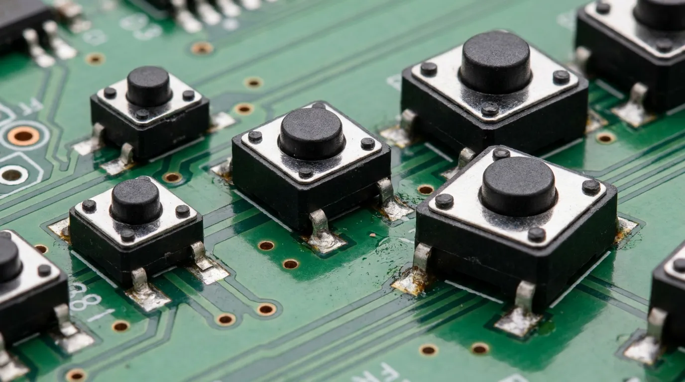
An SMD tactile switch is a momentary-contact, surface-mounted push-button switch that provides a distinct tactile click when pressed. It is placed directly onto the surface of a PCB — rather than through drilled holes — and is soldered using automated reflow techniques during standard SMT (Surface Mount Technology) assembly.
In simple terms: when you press it, the circuit closes and the device registers the input. When you release it, the circuit opens and the switch returns to its original state. The "tactile" part refers to the physical feedback — a short, crisp click — that confirms the switch has been actuated. This is fundamentally different from a soft-touch or capacitive button, which provides no mechanical confirmation.
SMD tactile switches are widely used because they combine small physical size, reliable actuation, high compatibility with automated PCB assembly, and a broad range of specifications to match different applications.
How an SMD Tactile Switch Works
Internal Structure and Components
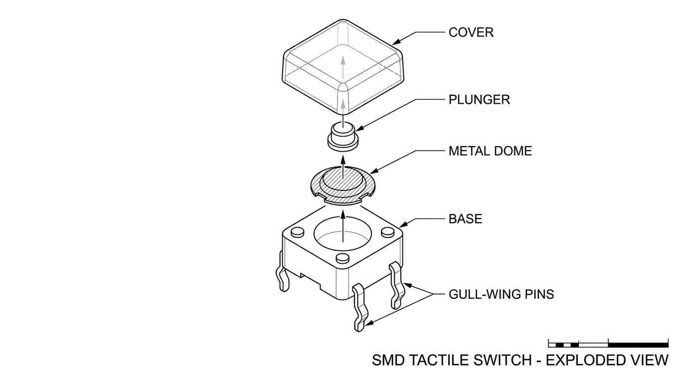
The SMD tactile switch is built from five core components: the cover, the button (actuator/plunger), the metal dome, the base, and the pins (terminals).
- Cover: A molded protective shell that seals the internal components against dust and contaminants. On sealed variants, this cover provides IP-rated protection.
- Button/Plunger: The part that transfers external pressing force down onto the metal dome.
- Metal dome: The mechanical heart of the switch. It is a precisely formed thin metal disc that holds a curved shape under normal conditions.
- Base: A molded resin housing that holds the terminals and forms the PCB contact surface.
- Pins/Terminals: The electrical contacts that connect the switch to the PCB circuit. In SMD types, these are surface pads rather than through-hole leads.
The Metal Dome Actuation Mechanism
When you press the button, the plunger pushes down on the metal dome. The dome deflects inward under the applied force, makes contact with the solder tab or central contact point at the base, and completes the circuit between the two sets of pins. The moment the dome snaps inward, you feel and hear the click — that is the tactile feedback.
When you remove your finger, the dome springs back to its original curved shape, separating from the contact point and opening the circuit again. This action is instantaneous and consistent, which is why metal dome-based tactile switches are preferred over conductive rubber alternatives in most precision applications. Conductive rubber switches function similarly but produce softer feedback and have significantly higher contact resistance, making them unsuitable where reliable, low-resistance contact is critical.
SMD vs. Through-Hole Tactile Switches: Which Is Right for Your PCB?
This is one of the most common decisions engineers face when specifying a tactile switch. The answer depends on your board density, assembly process, application environment, and design priorities.
| Feature | SMD Tactile Switch | Through-Hole (THT) Tactile Switch |
|---|---|---|
| Board footprint | Minimal — sits on surface, no drilled holes | Larger — requires drilled holes and component height above board |
| Assembly | Automated pick-and-place + reflow soldering | Often hand-soldered or wave-soldered |
| Board density | Excellent for high-density, compact designs | Occupies more board area and height clearance |
| Mechanical strength | Good with support pads; lower than THT in high-vibration conditions | Superior mechanical anchoring via soldered leads through the board |
| Repairability | Requires hot-air rework tools; more difficult | Easier to desolder and replace by hand |
| IP rating availability | IP65 and IP67 sealed variants available | IP65 and IP67 variants also available |
| Production cost (volume) | Lower at scale due to automation compatibility | Higher due to manual assembly steps |
| Best for | Compact PCBs, wearables, IoT, consumer electronics | Industrial panels, high-vibration environments, products requiring easy field repair |
For most modern, space-constrained designs — smartphones, wearables, medical handhelds, compact IoT modules — SMD is the preferred choice. Through-hole tactile switches remain a solid option when mechanical durability under vibration or easy field replacement is the primary requirement.
If you need to evaluate all mounting styles together, the full tact switch range at HX-Switch covers through-hole, SMD, and other variants with comparative detail.
Key Specifications of SMD Tactile Switches Explained
Selecting the right SMD tactile switch requires understanding what each specification actually means for your design. Here are the parameters that matter most.
Body Size and Footprint
SMD tactile switches are available in standardized body sizes, typically expressed as width × depth in millimeters. The most common footprints are:
| Body Size | Common Use Context |
|---|---|
| 3 × 3 mm | Ultra-compact wearables, earbuds, ultra-thin devices |
| 4 × 4 mm | Smartphones, handheld remotes, medical devices |
| 5 × 5 mm | IoT modules, compact industrial interfaces |
| 6 × 6 mm | General-purpose compact PCBs, controllers |
Choosing the correct body size is not only about physical space — it directly affects the PCB land pattern dimensions, pad layout, and the available actuator height options for that footprint.
Actuation Force
Actuation force, measured in gram-force (gf), is the amount of downward pressure required to actuate the switch. This is one of the most important user-experience parameters. Choose too light and the switch triggers unintentionally; choose too heavy and users find the product uncomfortable or unresponsive.
| Application Type | Recommended Actuation Force |
|---|---|
| Wearables, earbuds, thin consumer devices | 100 – 150 gf |
| Smartphones, remote controls, general consumer | 150 – 180 gf |
| Handheld instruments, medical devices | 160 – 220 gf |
| Industrial controls, rugged environments | 220 – 260 gf+ |
Actuator Height
The actuator height determines how far the button protrudes above the PCB surface. Ultra-low-profile SMD switches can have actuator heights below 1 mm, while standard configurations range from 1.5 mm to 5 mm or more. Match the actuator height to your enclosure design — the button travel must align precisely with the keyhole or silicone overmold in your housing.
Cycle Life and Durability
The rated cycle life tells you how many actuations the switch is designed to survive reliably. Standard SMD tactile switches are typically rated at 100,000 cycles. More robust variants are available at 500,000 cycles for frequent-use applications, with premium long-life options reaching 1,000,000 to 2,000,000 cycles for high-frequency industrial use. Match the cycle life to your product's expected daily usage and design lifespan.
IP Rating and Sealing Options
Unsealed SMD tactile switches are appropriate for enclosed, dry environments where the PCB is protected inside a sealed housing. If your PCB is exposed to dust, moisture, condensation, or liquids — even partially — specify a sealed SMD tactile switch. IP65-rated switches offer dust-tight protection and resistance to water jets. IP67-rated variants withstand temporary submersion. Sealed SMD switches achieve this through a rubber gasket under the cover or a fully molded housing.
SMD Tactile Switch Termination Styles
Not all SMD tactile switches terminate to the PCB in the same way. The termination style affects pad layout, solder joint visibility, mechanical stability, and rework difficulty.
Gull-wing leads extend outward from the switch body and curve down to the PCB surface. They are easy to visually inspect after reflow and work well with standard stencil printing. This is the most common termination on standard SMD tactile switches.
SMD tab termination uses flat metal tabs that sit flush under the body of the switch, soldering directly onto flat pads. This offers a lower overall profile and a smaller footprint but requires precise pad design since the joints are hidden under the component body.
J-lead termination curves the lead under the component body in a J-shape, offering a compact pad layout with reasonable inspection access.
Always verify the termination style in the manufacturer's datasheet before finalizing your PCB land pattern, as mixing pad layouts between termination types will produce unreliable solder joints.
PCB Footprint and Layout Best Practices for SMD Tactile Switches
This is where many PCB designs run into problems. Even a correctly specified SMD tactile switch will fail prematurely or produce inconsistent actuation if the PCB layout is not done correctly.
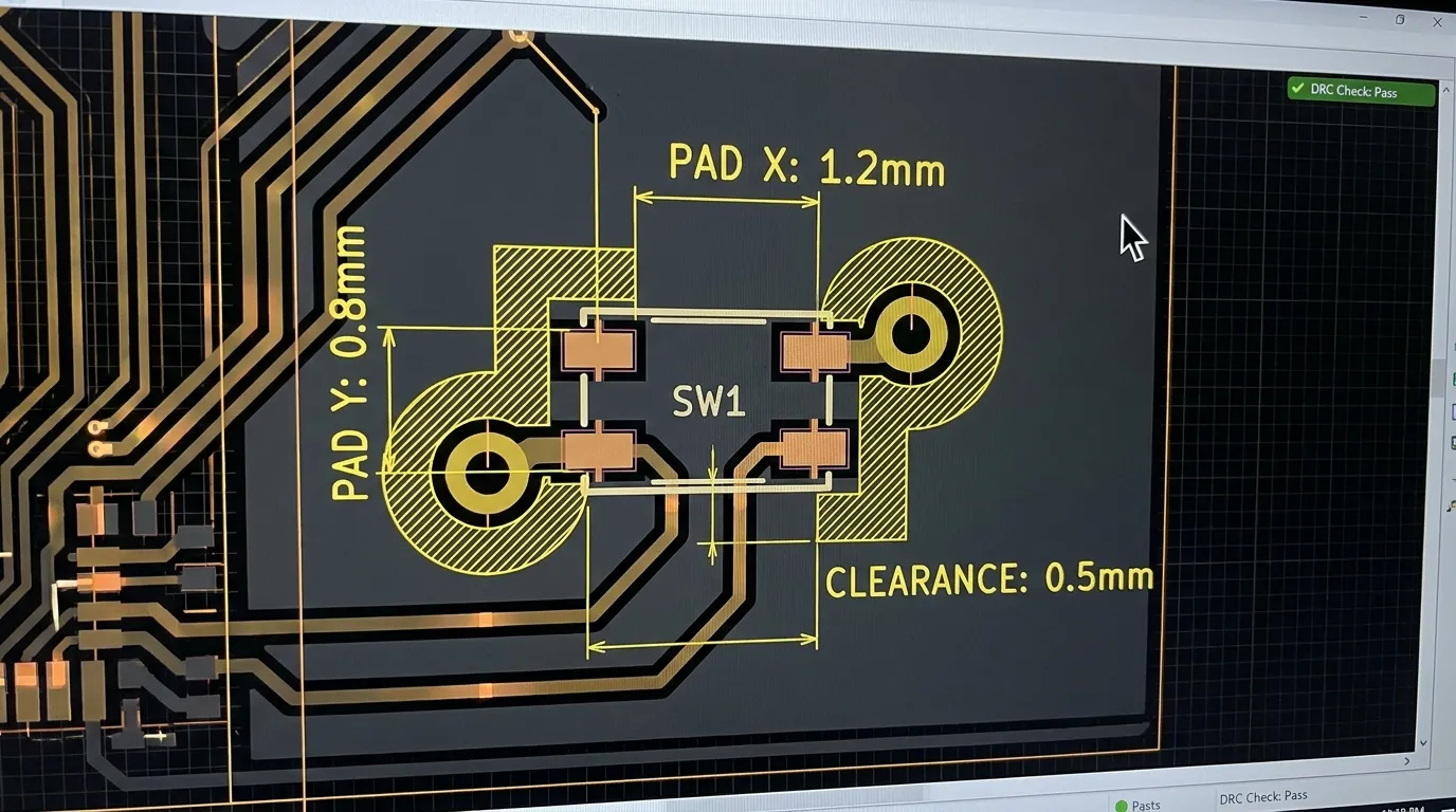
Pad Dimensions and Land Pattern
Always use the pad dimensions specified in the switch manufacturer's datasheet. These dimensions are calculated to deliver the correct solder volume for reliable joint formation during reflow. Using generic or estimated pad sizes risks cold joints, insufficient adhesion, or bridging between adjacent pads. If a recommended land pattern is not in the datasheet, contact the supplier before designing the footprint.
Component Clearance and Spacing
Maintain adequate spacing between the SMD tactile switch and neighboring components. Tall components placed too close can obstruct the actuator or complicate reflow airflow. Keep a minimum of 0.5 mm clearance around the switch body on all sides, and verify that no component taller than the actuator height is placed within the actuation zone.
Mechanical Support Pads
For switches subject to repeated user pressing, add mechanical support pads in your PCB design. These are non-functional copper pads that extend the solder adhesion area, distributing mechanical stress from repeated actuation across a larger contact surface rather than concentrating it at the signal pads alone. Skipping support pads is a common cause of pad lifting on compact consumer boards.
Vias and Trace Routing
Do not place vias directly on or adjacent to switch pads. During reflow, solder paste can wick into via holes and starve the pad joint. Position vias at least 4–8 mils away from pad edges. Keep switch signal traces short, route them away from high-frequency or power traces, and use pull-up or pull-down resistors on GPIO inputs to prevent floating logic states when the switch is not pressed.
Stencil Aperture Design
Design stencil apertures to deliver the correct solder paste volume for each pad. Over-printing causes bridging; under-printing causes insufficient joints. Follow the switch manufacturer's stencil guidelines, as SMD tactile switches with small pads are particularly sensitive to paste volume variation.
Tip: Always request the manufacturer's recommended land pattern and stencil aperture data before completing your PCB layout. These documents prevent the most common assembly failures before they reach production.
How to Choose the Right SMD Tactile Switch for Your Application
The best SMD tactile switch for your design is the one that aligns all relevant specifications — size, force, height, lifecycle, and IP rating — with the specific demands of your product and its users.
Consumer Electronics and Wearables
Space is the primary constraint. Choose the smallest body size that fits your footprint (3×3 mm or 4×4 mm), an actuation force between 100–160 gf for comfortable repeated use, and an ultra-low-profile actuator height to stay within the thin device envelope. Lifecycle requirements are moderate (100,000–500,000 cycles) unless the button is a primary navigation input used dozens of times per day.
Industrial and Medical Equipment
Reliability and tactile clarity matter more than miniaturization here. Select switches with a higher actuation force (200–260 gf) to prevent accidental activation, a lifecycle rated at 500,000 cycles or more, and IP65 or IP67 sealing if the device is used in clinical, outdoor, or industrial environments. Confirm RoHS compliance for medical or EU-market applications.
IoT and Compact PCB Modules
IoT boards often need both small size and environmental resilience. A 4×4 mm or 5×5 mm SMD tactile switch with a moderate actuation force (150–200 gf) and IP-rated sealing offers the right balance. For battery-powered devices, ensure the switch GPIO configuration includes pull-up or pull-down resistors to avoid leakage current on floating inputs.
Common Applications of SMD Tactile Switches
SMD tactile switches are found in a wide range of products across industries:
- Consumer electronics: smartphones, tablets, remote controls, gaming controllers, wireless earbuds, smart speakers
- Wearable technology: smartwatches, fitness trackers, medical wearables, hearables
- Medical devices: handheld diagnostic instruments, infusion pumps, portable monitors
- Industrial controls: compact HMI panels, programmable logic controllers, sensor modules
- Automotive: dashboard controls, infotainment systems, steering wheel switches
- IoT products: smart home sensors, Wi-Fi modules, environmental monitors, smart meters
- Telecommunications: routers, modems, network switches, VoIP handsets
The common thread across all these applications is the need for a small, reliable, momentary input component that integrates cleanly with automated PCB assembly processes.
Mistakes to Avoid When Using SMD Tactile Switches in PCB Designs
| Mistake | Consequence | Correct Approach |
|---|---|---|
| Using incorrect pad dimensions | Cold or insufficient solder joints; switch lifts off under mechanical stress | Always use manufacturer datasheet land pattern |
| Skipping mechanical support pads | Pad lifting after repeated actuations; premature PCB failure | Add mechanical anchor pads to the land pattern design |
| Placing vias on or near switch pads | Solder wicks into vias; starved pad joints | Keep vias minimum 4–8 mils from pad edges |
| Ignoring actuation force for user context | Button feels wrong; too easy to accidentally trigger or too hard to press | Match force (gf) to application and expected user behavior |
| Selecting unsealed switch for exposed environments | Dust or moisture contamination causes intermittent contact failure | Specify IP65/IP67 sealed SMD switch for any exposed PCB location |
| Incorrect reflow temperature profile | Thermal damage to dome or housing; joint failure | Follow manufacturer's reflow recommendation; confirm solder paste compatibility |
| Mismatching actuator height to enclosure design | Switch does not align with housing button cutout; poor tactile feel | Confirm actuator height with mechanical team before PCB finalization |
Related Guides
Understanding SMD tactile switches is an important step, but the right component choice often depends on understanding the full product family alongside it.
If you are evaluating all tact switch types for your design — including through-hole variants, illuminated tact switches, and long-life options — the complete tact switch selection guide at HX-Switch gives a detailed overview of the full range with product specifications across all mounting styles.
Frequently Asked Questions About SMD Tactile Switches
What is an SMD tactile switch?
An SMD tactile switch is a surface-mounted, momentary push-button switch that uses a metal dome mechanism to provide a distinct tactile click when actuated. It is soldered directly onto the surface of a PCB without drilling through the board.
How does an SMD tactile switch work?
Pressing the actuator pushes down on the internal metal dome, deflecting it until it contacts the circuit terminal and closes the circuit. When pressure is released, the dome springs back to its original shape and the circuit opens again. The snap of the dome inward creates the audible and tactile feedback characteristic of this switch type.
What is the difference between SMD and through-hole tactile switches?
SMD switches mount on the PCB surface and are compatible with automated pick-and-place assembly, making them ideal for compact, high-density boards. Through-hole switches insert through drilled PCB holes and offer stronger mechanical anchoring, making them preferable for high-vibration applications or products requiring easy field repair. SMD switches are generally smaller, faster to assemble in volume, and less costly at scale.
What sizes do SMD tactile switches come in?
The most common body sizes are 3×3 mm, 4×4 mm, 5×5 mm, and 6×6 mm. Actuator heights range from under 1 mm for ultra-low-profile designs to over 5 mm for standard panel-flush applications.
What actuation force should I choose for my SMD tactile switch?
For light-touch consumer devices and wearables, 100–160 gf is appropriate. For handheld instruments and medical equipment, 160–220 gf provides clear confirmation without excessive effort. For industrial controls where accidental activation must be prevented, 220–260 gf or higher is recommended.
Can SMD tactile switches be waterproof?
Yes. Sealed SMD tactile switches are available with IP65 and IP67 ratings. IP65 provides protection against dust ingress and low-pressure water jets. IP67 provides protection against short-term submersion up to 1 meter. These use rubber gaskets or sealed cover assemblies to protect the internal dome and contact mechanism.
What is the typical lifecycle of an SMD tactile switch?
Standard SMD tactile switches are rated at 100,000 cycles. Higher-endurance variants are available at 500,000 cycles or more. Premium long-life switches designed for high-frequency industrial or commercial use can be rated at 1,000,000 to 2,000,000 actuation cycles.
What causes SMD tactile switch failure on PCBs?
The most common causes are pad lifting due to missing mechanical support pads, solder joint failure from incorrect pad dimensions or reflow profile, dome contamination in unsealed switches exposed to moisture, and actuation inconsistency from mismatched actuator height relative to the product enclosure. All of these are preventable with correct design practices.
Are SMD tactile switches compatible with automated PCB assembly?
Yes — this is one of their primary advantages. SMD tactile switches are designed for automated pick-and-place equipment and standard reflow soldering processes, making them highly efficient for volume production compared to through-hole switches that often require hand-soldering.
Conclusion
SMD tactile switches are the practical choice for compact PCB designs where board space is limited, automated assembly is standard, and reliable user input is essential. The key to getting them right is selecting the correct combination of body size, actuation force, actuator height, lifecycle rating, and IP protection for your specific application — and then designing a PCB land pattern that supports long-term mechanical and electrical reliability.
Take the time to match actuation force to your user context, validate your pad layout against the manufacturer's recommended land pattern, and add mechanical support pads on any board that will experience repeated press loads. These decisions cost nothing at the design stage and prevent significant failures in production or the field.
For a full overview of the tact switch product family — including through-hole options, illuminated variants, and long-life configurations — explore the complete tact switch range at HX-Switch to find the specification that fits your design requirements.