





How to Read a Tactile Switch Datasheet Before Ordering
Most ordering mistakes with tact switches don't happen because of a wrong product search. They happen because the buyer opened a datasheet, scanned the numbers, and assumed the switch would work. A datasheet is the only binding technical document between you and the factory. If you misread one specification — or skip a section entirely — you can end up with a switch that fails in production, triggers a PCB redesign, or simply feels wrong in the hands of the end user.
This guide walks you through every key section of a tactile switch datasheet, what each specification actually means, what values are acceptable for different applications, and what warning signs to watch for before you place a sample or bulk order. Whether you are a PCB engineer evaluating a new component, a procurement officer qualifying a supplier, or a product manager reviewing a bill of materials, this article gives you the practical knowledge to read a tact switch datasheet with confidence.
What a Tactile Switch Datasheet Typically Contains
A standard tact switch datasheet is divided into four main sections: mechanical specifications, electrical specifications, environmental specifications, and dimensional drawings. Most datasheets also include an ordering code table, a circuit diagram, and a recommended PCB land pattern or hole dimension table.
If a supplier datasheet is missing any of these sections — particularly the electrical specs or dimensional drawing — that is itself a quality signal worth noting before you proceed.
Here is the structure you should expect when you open a standard tactile switch datasheet:
| Datasheet Section | What It Covers |
|---|---|
| Mechanical Specifications | Operating force, travel distance, actuator height, body dimensions |
| Electrical Specifications | Rated voltage/current, contact resistance, insulation resistance, dielectric strength |
| Environmental Specifications | Operating temperature, storage temperature, IP rating |
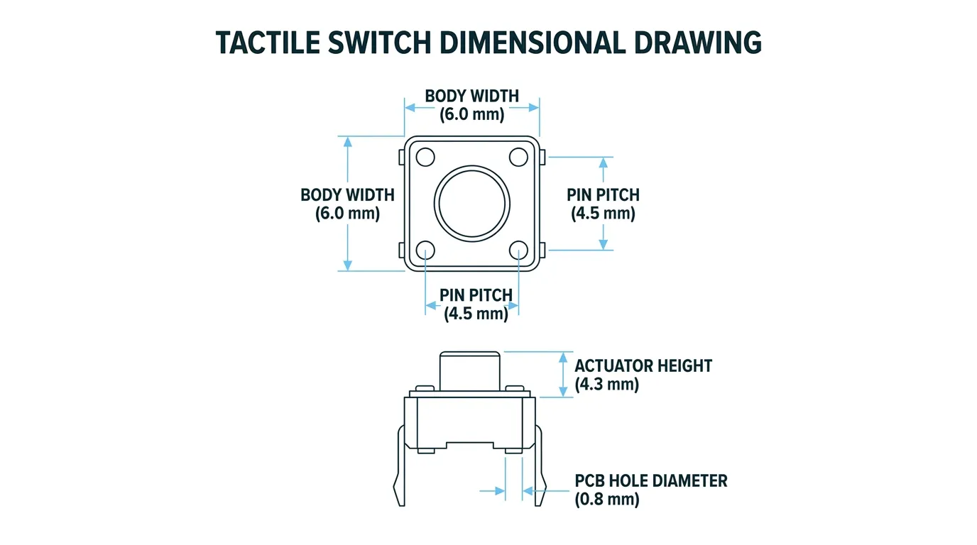
| Dimensional Drawing | Body footprint, actuator height, pin pitch, PCB hole diameter |
| Ordering Code Table | How to decode the part number for specific configurations |
| Circuit Diagram | Internal contact arrangement (SPST-NO or others) |
Mechanical Specifications: What to Check First
Operating Force (Actuation Force)
Operating force — sometimes called actuation force — is the amount of pressure required to depress the switch and trigger a signal. It is expressed in gram-force (gf) or Newtons (N). The two units are directly related: 1 N ≈ 102 gf.
Standard tact switches are available in a wide range of actuation forces. The most common values range from 100 gf to 320 gf, depending on application type.
| Operating Force | Feel | Typical Application |
|---|---|---|
| 100–130 gf | Very light touch | Handheld devices, wearables, children's electronics |
| 160 gf | Standard light press | Consumer electronics, remote controls, computer peripherals |
| 200–260 gf | Firm, deliberate press | Industrial controls, automotive panels, medical devices |
| 300–320 gf | Heavy press | Safety-critical or anti-accidental-actuation applications |
The operating force value in the datasheet is typically listed as a nominal with a tolerance, such as 160 gf ± 50 gf. If a datasheet shows only a single number without a tolerance, ask the supplier directly. A tolerance of ±50 gf is standard; a supplier who cannot provide this is worth flagging.
Choosing the wrong actuation force is one of the most common pre-order mistakes. Too light, and the switch will be accidentally triggered. Too heavy, and the user experience suffers, especially in consumer products with frequent button interactions.
Travel Distance (Stroke and Pre-Travel)
Travel distance refers to how far the actuator physically moves from its resting position to the fully actuated position. Most tact switch datasheets express this as total travel or stroke, with a typical range of 0.25 mm to 0.35 mm.
Some datasheets distinguish between:
- Pre-travel: the distance from rest to the point where the click (contact closure) occurs
- Overtravel: the remaining movement after contact closure, before the switch bottoms out
For applications where precise actuation timing matters — such as gaming controllers or high-speed signal input — pre-travel vs. total travel can affect the user experience meaningfully. For most standard PCB applications, total travel is the only figure you need to review.
Actuator Height and Body Dimensions
The actuator height is the distance from the top of the PCB to the tip of the switch's button. This is a critical measurement, not an aesthetic one. If your product has an overlay, a tactile membrane, or a bezel above the PCB, the actuator must be tall enough to make contact — but not so tall that it creates misalignment or mechanical stress.
Body footprint is equally important. The most common standard body size for through-hole tact switches is 6×6 mm, with SMD variants available in 4.5×4.5 mm, 5×5 mm, and 6×6 mm configurations.
Always cross-reference the dimensional drawing in the datasheet (not just the spec list) before approving a footprint. If you need a non-standard height or footprint, request a custom configuration — you can review available options through this custom tactile switch guide.
Electrical Specifications: The Safety-Critical Section
Rated Voltage and Current
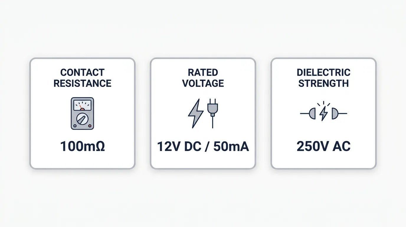
The electrical rating of a tact switch defines its safe operating range. Most standard tact switches carry a rating of 50 mA at 12 V DC. This is sufficient for most logic-level and low-power digital circuits, which is the primary application for tact switches.
Do not confuse rated voltage with maximum voltage. The rated voltage is the intended continuous operating condition. The maximum voltage is an absolute ceiling — operating close to or at the maximum voltage significantly shortens switch life and increases the risk of contact arcing.
For industrial or higher-power applications, verify that the switch's rated current and voltage match your circuit's actual requirements. A switch rated at 50 mA / 12 V DC should never be used in a 24 V industrial circuit without explicit confirmation from the supplier that the switch is qualified for that range.
Contact Resistance
Contact resistance is the electrical resistance measured at the switch contacts when the switch is in the closed (actuated) position. It is measured in milliohms (mΩ).
The industry standard maximum for contact resistance in tact switches is 100 mΩ initial value. Premium specifications — particularly for gold-plated contacts — often achieve ≤50 mΩ.
Why does this matter? High contact resistance causes two problems. First, in low-power logic-level circuits (where signal currents may be as low as 1 mA), even a modest resistance can degrade the signal integrity. Second, over thousands of cycles, elevated contact resistance generates microscopic heat at the contact point, accelerating wear.
| Contact Material | Typical Resistance | Best For |
|---|---|---|
| Silver (standard) | ≤100 mΩ | Standard digital/logic circuits |
| Gold-plated | ≤50 mΩ | Low-current signal lines, sensitive electronics |
If a supplier's datasheet leaves the contact resistance field blank, that is a significant red flag. This specification should always be stated — it is one of the clearest indicators of contact quality.
Insulation Resistance and Dielectric Strength
These two specifications describe the switch's electrical isolation performance when the contacts are open.
Insulation resistance is the resistance between the open contacts (or between contacts and ground). It should be a very high value — typically ≥100 MΩ at 250–500 V DC. A low insulation resistance value means current can leak through the switch even when it is not actuated, which can cause false triggering or circuit errors.
Dielectric strength (also called withstand voltage) is the maximum AC voltage the switch can withstand between its open contacts without electrical breakdown. The standard test value is 250 V AC for 1 minute. Some higher-quality or industrial-grade switches are tested at 500 V AC.
These specifications are especially important for applications in humid environments, medical devices, or any circuit where the switch is adjacent to higher-voltage components.
Mechanical Life: How Long Will the Switch Actually Last?
The mechanical life rating — also called operating life or lifecycle — is the number of actuations a switch is rated to perform before its contact resistance, force feel, or physical integrity degrades below specification. This is expressed in cycles.
Common lifecycle ratings you will see in tact switch datasheets:
| Lifecycle Rating | Typical Application |
|---|---|
| 30,000–50,000 cycles | Basic consumer electronics, low-use devices |
| 100,000 cycles | Standard consumer electronics, remote controls |
| 500,000 cycles | Frequently-used controls, gaming controllers, industrial HMI |
| 1,000,000+ cycles | High-cycle industrial applications, medical devices |
The number on its own is meaningless without context. Here is how to translate it:
Lifecycle ÷ estimated daily presses = switch lifespan in days
For example, a TV remote control button pressed an average of 30 times per day, using a switch rated at 100,000 cycles: 100,000 ÷ 30 = 3,333 days ≈ 9 years. That is likely sufficient. The same switch used as a gaming controller button pressed 500 times per day would last only 200 days — clearly insufficient.
Higher actuation force switches (260–320 gf) tend to have lower lifecycle ratings than light-force variants, because the metal dome undergoes greater mechanical stress per actuation.
If you are ordering in large volumes, lifecycle expectations directly affect your warranty risk. For more on aligning lifecycle requirements with bulk purchasing decisions, the tactile switch wholesale guide covers this in more detail.
Environmental Specifications: Sealed vs. Standard
IP Rating Explained
IP (Ingress Protection) rating is a standardized code that defines a switch's resistance to solid particles (dust) and liquids (water). Not all tact switches carry an IP rating — standard unsealed switches are only appropriate for clean, dry indoor PCB environments.
| IP Rating | Dust Protection | Liquid Protection | Typical Application |
|---|---|---|---|
| No rating | None | None | Indoor PCBs, standard consumer electronics |
| IP40 | Protected from >1 mm solids | No liquid protection | Light industrial, office equipment |
| IP54 | Dust-protected | Protected from water splashes | Kitchen appliances, automotive dashboards |
| IP60 | Fully dustproof | No liquid protection | Outdoor electronics, dust-heavy industrial |
| IP67 | Fully dustproof | Submersion up to 1 m for 30 min | Outdoor devices, medical, industrial HMI |
Sealed switches rated IP67 are specifically engineered with a sealed housing that prevents contaminants from reaching the internal dome and contacts. If you order an unsealed switch for an IP67 application, no amount of PCB coating or enclosure design fully compensates for the switch itself being an ingress point.
Always confirm whether an IP rating in a supplier datasheet is self-declared or independently tested. Reputable suppliers will specify the test standard reference (IEC 60529 is the international standard for IP ratings). If the datasheet simply says "waterproof" without an IP code or test reference, treat it as unverified.
Operating and Storage Temperature Range
Standard tact switches are rated for –20°C to +70°C operating and –20°C to +85°C storage. Some industrial and automotive-grade switches extend this to –40°C operating and +105°C or higher storage.
If your product operates in an automotive cabin, outdoor enclosure, or near a heat-generating component, verify that both the operating and storage temperature ranges match your real-world conditions — not just the nominal operating temperature.
How to Read the Dimensional Drawing
The dimensional drawing is the most practically important section of a tact switch datasheet for PCB designers, yet it is also the section most likely to be misread. The drawing typically includes:
- Top view: body outline, pin positions, footprint dimensions (length × width)
- Side view: total body height, actuator height above body top, pin length below PCB
- Pin/pad layout: spacing between pins (pitch), pin diameter for through-hole or pad size for SMT
- Recommended PCB hole diameter: for through-hole types, the suggested drill size (commonly 1.0–1.3 mm)
A common mistake is confusing actuator height (measured from the PCB surface to the top of the button) with body height (the height of the switch housing only). These are different measurements. Your product's overlay or front panel thickness determines which height you need to specify when ordering.
Pin pitch and body footprint must match your PCB layout exactly. Even a 0.2 mm error in pin pitch will cause a switch to be misaligned in the PCB holes, leading to solder bridges or mechanical stress during assembly.
Ordering Code / Part Number Structure
Most tact switch suppliers encode key specifications directly into the product part number. Understanding the ordering code structure lets you verify that what you ordered is exactly what was quoted.
A typical ordering code structure looks like this:
Example: TS-A6PG-T160
Each segment of the code may represent:
- Switch series or body size (e.g., A6 = 6×6 mm body)
- Mounting type (P = through-hole, S = SMT)
- Configuration or terminal style (G = standard terminal)
- Operating force (T160 = 160 gf)
The decoding table for the ordering code is always included at the end or bottom of a supplier datasheet. Always read this table before placing an order. Changing a single character in the part number — for example, T160 to T260 — changes the actuation force from 160 gf to 260 gf, which is a completely different product feel. This error happens regularly in procurement, especially when ordering multiple variants.
If you are sourcing directly from a factory, a reliable China tact switch supplier will provide a clear ordering code guide in their datasheet and confirm the configuration in writing before production.
Red Flags in a Supplier Datasheet
Not all datasheets are created equal. Factory-produced datasheets from smaller manufacturers sometimes omit critical specifications or present data in ways that make it difficult to verify quality. Here are the most important warning signs:
| Red Flag | What It Signals | What to Ask the Supplier |
|---|---|---|
| Contact resistance field is blank or missing | Factory does not test or cannot guarantee contact quality | Request test reports and specify ≤100 mΩ in the purchase order |
| Lifecycle rating not stated | Switch may fail well below expectations | Ask for the test standard and rated cycle count in writing |
| "Sealed" or "waterproof" label without an IP code | Unverified environmental claim | Request the IP rating and IEC 60529 test reference |
| No dimensional drawing in datasheet | Impossible to verify PCB footprint compatibility | Request a full mechanical drawing (DXF or PDF) |
| Operating force stated without tolerance | Only nominal value, actual variance unknown | Ask for the tolerance band (standard is ±30–50 gf) |
| Temperature range missing from datasheet | Environmental performance is unverified | Request the operating and storage temperature test data |
| Mixed or inconsistent units (gf and N used interchangeably) | Datasheet may have been assembled carelessly | Cross-check all values and request clarification |
A complete, well-structured datasheet is one of the most reliable proxy indicators of a supplier's manufacturing discipline. If the technical documentation is incomplete, the product quality may reflect that same gap. For a full framework on evaluating supplier quality before a large purchase, the bulk tact switches buying guide covers supplier qualification in detail.
Tactile Switch Datasheet — Pre-Order Checklist
Before you approve any tact switch order based on a supplier datasheet, confirm each of the following:
| Specification | What to Check | Acceptable Standard |
|---|---|---|
| Operating force | Stated with tolerance | 100–320 gf, ±30–50 gf tolerance |
| Travel / stroke | Total travel confirmed | Typically 0.25–0.35 mm |
| Actuator height | Matches PCB/overlay design | Confirmed against product design |
| Body footprint | Verified against PCB layout | Exact mm match, not approximate |
| Rated voltage / current | Within circuit operating range | Typically 12 V DC / 50 mA |
| Contact resistance | Explicitly stated | ≤100 mΩ (≤50 mΩ for gold contacts) |
| Insulation resistance | Explicitly stated | ≥100 MΩ |
| Dielectric strength | Explicitly stated | ≥250 V AC / 1 min |
| Lifecycle rating | Matches application use pattern | 100,000+ cycles for most consumer use |
| IP rating | Confirmed for environment | IP67 for wet/outdoor; none for indoor PCB |
| Operating temperature | Covers application range | Min. –20°C to +70°C for standard use |
| RoHS compliance | Marked on datasheet | Required for EU markets |
| Ordering code | Decoded and confirmed | Cross-referenced against spec table |
| Dimensional drawing | Full drawing present | Includes top, side view, pin pitch |
Common Mistakes to Avoid
Designing at the maximum voltage. The maximum voltage in a datasheet is a failure ceiling, not an operating recommendation. Always design at or below the rated voltage.
Treating lifecycle as an unlimited guarantee. A 100,000-cycle rating means the switch is tested to meet its contact resistance and actuation force specs for that many cycles. It does not mean the switch will fail precisely at cycle 100,001. But designing a product that pushes a 50,000-cycle switch to 80,000 actual cycles is an unnecessary risk.
Ordering a standard switch for a sealed application. If your product will face humidity, water splashing, or outdoor exposure, an IP-rated switch is not optional. Relying on a product enclosure to compensate for a non-sealed switch leaves a single mechanical failure point that no enclosure can fully eliminate.
Confusing actuator height with body height. These two dimensions serve different purposes. Actuator height determines whether the switch button reaches the user's finger through an overlay. Body height determines PCB clearance. Mixing them up in your design review causes real assembly problems.
Skipping the ordering code decode. Procurement teams often copy-paste part numbers without reading the ordering code table. A single character change in a supplier's part number can change the actuation force, height, or sealing class. Always decode the part number field by field before finalizing the order.
Related Guides
If you are at the stage of selecting between supplier options or planning a larger procurement, the complete tact switch guide covers the full product family — types, configurations, applications, and sourcing overview — and is a useful reference once you have confirmed your specification requirements from the datasheet.
For buyers sourcing directly from China-based factories, understanding how to evaluate factory datasheets and request proper documentation is covered in the tact switch supplier China guide. If your project involves non-standard specifications — custom height, custom actuation force, or custom housing — the custom tactile switch guide explains how to work with a manufacturer to define those parameters correctly.
FAQs About Tactile Switch Datasheets
What is a normal operating force for a tactile switch?
Most standard tact switches fall between 100 gf and 260 gf. Light-touch applications (consumer remotes, wearables) use 100–160 gf. Industrial and automotive panels typically use 200–260 gf. The operating force should always be listed with a tolerance in the datasheet — a typical tolerance band is ±30–50 gf.
What is contact resistance in a tactile switch datasheet?
Contact resistance is the electrical resistance at the switch contacts when the switch is in the closed position. The industry-standard maximum is 100 mΩ. Gold-contact premium switches often achieve ≤50 mΩ. High contact resistance degrades signal quality and shortens switch life in high-cycle applications.
What does dielectric strength mean on a tact switch datasheet?
Dielectric strength is the maximum AC voltage the switch can withstand across its open contacts without electrical breakdown. The standard test value is 250 V AC for 1 minute. Some industrial or sealed switches are rated at 500 V AC. This is not the same as the switch's operating voltage.
How do I calculate if the lifecycle rating is enough for my product?
Divide the lifecycle rating by your estimated daily presses: Lifecycle ÷ daily presses = lifespan in days. For example, 100,000 cycles ÷ 50 presses per day = 2,000 days ≈ 5.5 years. Always add a safety factor — design for 1.5–2× the calculated minimum.
What IP rating does a tact switch need for outdoor use?
IP67 is the recommended minimum for outdoor or wet-environment applications. IP67 means the switch is fully dustproof and can withstand submersion at 1 meter for 30 minutes. IP54 is sufficient for splash-resistant environments such as kitchen appliances or dashboard panels. Standard unmarked switches are not suitable for any moisture-exposed environment.
What is the difference between rated voltage and maximum voltage in a datasheet?
Rated voltage is the intended continuous operating voltage — typically 12 V DC for most tact switches. Maximum voltage is the absolute upper limit. Always design at or below the rated voltage. Operating at maximum voltage shortens switch life and increases arc risk, particularly in higher-cycle applications.
Can I trust specifications on a China factory tact switch datasheet?
Most factory datasheets from established China tact switch manufacturers accurately reflect their tested specifications. However, some smaller factories omit test tolerances, leave specifications blank, or use unverified claims like "waterproof" without an IP code. Before placing a bulk order, request a product sample, confirm contact resistance with a test report, and verify IP ratings against a test standard reference. A qualified China tact switch supplier should provide complete documentation without hesitation.
What should I do if the datasheet is missing a dimensional drawing?
Do not order without a dimensional drawing. A missing drawing means you cannot verify PCB footprint compatibility. Request a full mechanical drawing in PDF or DXF format from the supplier before approving any sample or production order.
Conclusion
A tactile switch datasheet contains everything you need to make a correct ordering decision — but only if you know where to look and what the numbers actually mean. Operating force, contact resistance, lifecycle, IP rating, and dimensional accuracy are the five specifications that cause the most ordering problems when misread or ignored.
Work through each section of the datasheet systematically, use the pre-order checklist above, and treat any missing specification as a question that must be answered before the order is placed. A supplier who provides a complete, clearly specified datasheet is already demonstrating the product discipline you want behind your components.
If you need to evaluate multiple suppliers, compare specifications across datasheets, or qualify a factory for a high-volume programme, the tactile switch wholesale guide provides a structured framework for that process.
