





Custom Tactile Switch: Force, Height, LED & Sealing Guide
When you're designing a product for mass production, a standard off-the-shelf tact switch rarely fits your exact requirements. Your enclosure has a specific panel depth. Your users wear gloves. Your device operates in a wet or dusty environment. Your UI needs backlit feedback. Each of these demands a custom tactile switch built to your specification — not one chosen from a generic catalog.
This guide covers the four parameters that matter most in a custom tact switch: operating force, actuator height, LED integration, and environmental sealing. By the end, you'll know exactly what to specify before you contact a manufacturer. For a broader overview of tact switch types and mounting options, see the complete tact switch product range at Hanxia.
What Is a Custom Tactile Switch?
A custom tactile switch is a momentary push-button switch manufactured to a buyer-defined specification rather than a standard product configuration. In an OEM or private label context, "custom" means you define one or more of the following before the switch is produced: the actuation force, the actuator height, the LED color and type, the sealing level, the contact plating material, and sometimes the housing color or branding.
The switch itself still functions as a tactile momentary switch — it closes the circuit on press and opens it on release, providing a distinct physical click. What changes is how that switch behaves under force, how tall it sits on your PCB, whether it lights up, and how well it survives exposure to moisture or dust. These four parameters are independent, but they interact. A sealed, illuminated switch with a custom actuator height is achievable — but each variable narrows your available configurations. Knowing what you need before the RFQ saves weeks of revision.
Operating Force: Choosing the Right Actuation Strength
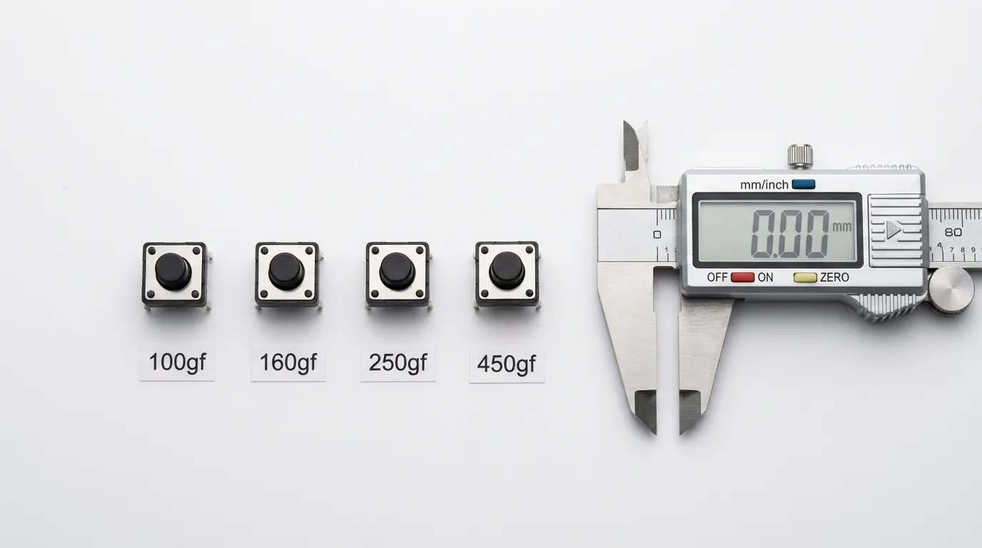
Operating force — measured in gram-force (gf) — defines how much pressure a user must apply to activate the switch. It is one of the most consequential specifications in a custom tact switch, and one of the most commonly misjudged.
Standard Force Ranges and What They Mean
Hanxia's tact switch lineup covers the four most common OEM force bands:
| Operating Force | Feel | Typical Application | User Profile |
|---|---|---|---|
| 100 gf | Very light touch | Wearables, remote controls, thin consumer devices | Fine-motor, no gloves, light use |
| 160 gf | Light-medium | Medical handhelds, smart home panels, IoT devices | General consumer, light industrial |
| 250 gf | Medium-firm | Industrial HMI panels, lab equipment, field devices | Regular gloved or ungloved use |
| 450 gf+ | Heavy | High-safety controls, outdoor rugged devices | Heavy gloves, intentional activation only |
These values refer to the peak actuation force — the maximum resistance felt just before the snap-over point. Lower force switches feel snappy and responsive; higher force switches resist accidental actuation in vibration-prone or gloved-operation environments.
How to Match Force to Your Application
The rule is simple: match force to the most demanding usage condition, not the average. If 10% of your users operate with gloves or in a vibrating environment, a 100 gf switch will cause phantom actuations. If you're designing a medical handheld where a light, deliberate press is standard, 450 gf will frustrate the user. For most general consumer electronics, 160 gf delivers the balance of responsiveness and accidental-press resistance that works across a broad audience.
A closely related variable is cycle life. Higher force switches tend to produce more wear on the contact dome over time. If your application demands 1 million+ cycles, confirm with the factory that the chosen force rating is available in their long-life variant — not all force options are available across all actuator types.
Actuator Height: Getting the Stack Right for Your PCB
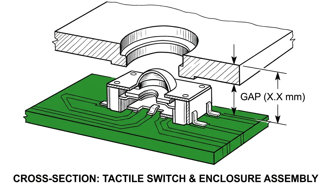
The actuator height determines how far the switch protrudes above the PCB surface. This directly governs whether the switch actuates properly through your enclosure's panel. Getting this wrong is one of the most common and costly OEM design errors.
Standard Height Options by Switch Body Size
For the most common 6×6mm body size, actuator heights typically range from 4.3mm to 20mm. For 3×3mm bodies, the range is narrower — typically 2.5mm to 8mm. Choosing the correct height requires knowing your PCB-to-panel gap precisely.
| Body Size | Actuator Height Range | Notes |
|---|---|---|
| 3×3 mm | 2.5 mm – 8 mm | Limited tall-height availability for SMD |
| 6×6 mm | 4.3 mm – 20 mm | Widest selection; most common OEM size |
| 12×12 mm | 4.5 mm – 16 mm | Heavier duty; industrial and automotive |
A key rule: the actuator height should be equal to or 0.3–0.5mm less than the PCB-to-panel gap. If the actuator height equals the panel gap exactly, there is no pre-travel and the switch will not snap properly. If the actuator is taller than the gap, the panel will permanently depress the switch — a failure mode that only shows up during enclosure assembly, not on the bench.
How Enclosure Design Affects Height Choice
For SMD-mounted switches, tall actuators (above 10mm) introduce mechanical leverage that can stress the solder joints under lateral force. If your actuator height exceeds 8mm on an SMD body, evaluate whether through-hole mounting is more appropriate for your application. Through-hole designs anchor mechanically to the PCB via pins, providing better resistance to side loads from tall actuators.
When building a panel-mount design with a custom keycap or button cap on top of the actuator, remember to subtract the cap travel distance from the height calculation. The cap adds effective height above the PCB surface; your measurement should reflect the net clearance inside the enclosure, not just the switch body height.
LED Integration: Illuminated Custom Tact Switches
LED integration turns a momentary push-button into a visual feedback element. For products where the user operates in low-light conditions — medical monitors, automotive dashboards, industrial control panels — an illuminated tact switch eliminates the need for a separate indicator LED on the PCB.
LED Types Available in Custom Tact Switches
The two primary LED configurations in OEM tact switch production are:
SMD LED (side-mounted or top-mounted): A surface-mount LED is positioned within the switch housing and solders to the PCB along with the switch contacts. This is the most compact option and works well for smaller body sizes (3×3mm, 4×4mm).
THT LED (through-hole): A separate LED pin passes through the PCB, allowing independent height adjustment and easier replacement. More common in 6×6mm and 12×12mm bodies where there is enough physical space.
| LED Type | Body Size Compatibility | Mounting | Color Options | Voltage Range |
|---|---|---|---|---|
| SMD LED | 3×3 mm, 4×4 mm, 6×6 mm | PCB pad | Single color, bi-color | 1.8V – 3.6V |
| THT LED | 6×6 mm, 12×12 mm | Through-hole pin | Single color, RGB | 2.0V – 3.6V |
| RGB LED | 6×6 mm, 12×12 mm | THT or SMD | Red, Green, Blue (individual control) | 2.0V – 3.6V per channel |
Specifying LED Color and Voltage for Your Product
When placing a custom LED tact switch order, specify: LED color (or RGB), forward voltage, and maximum continuous current (typically 20mA for standard LEDs, 5–10mA for long-life low-power designs). Mismatching the forward voltage to your PCB's drive circuit is one of the most common errors in illuminated switch integration — a 3.2V white LED driven at 5V without a current-limiting resistor will fail quickly.
For OEM products that ship globally, ensure your LED specification is consistent with the drive voltage of the circuit in all regional variants of your product. If the product has multiple hardware versions, specify the LED current draw and let the circuit designer calculate the resistor value rather than specifying a fixed resistance in the switch.
Applications Best Suited for Illuminated Tact Switches
Illuminated tact switches are the right choice when the switch's active state needs to be communicated visually to the operator — not just the device. Gaming peripherals, audio mixing consoles, automotive HVAC panels, and patient-call buttons in medical devices are all strong fits. In dark-operation environments, even a simple single-color LED transforms usability without adding significant BOM cost.
Sealing & IP Ratings: Waterproof Custom Tact Switch Options
Environmental sealing is the specification most frequently underestimated during OEM design. A switch that works perfectly in lab conditions can fail within weeks in a real-world deployment involving humidity, condensation, cleaning sprays, or outdoor exposure.
IP ratings (Ingress Protection) are defined under IEC 60529 and describe a switch's resistance to solid particles and liquids. The IP code is written as "IP" followed by two digits — the first for dust protection (0–6), the second for water protection (0–9K).
Common IP Ratings for Tactile Switches Explained
| IP Rating | Dust Protection | Water Protection | Typical OEM Application |
|---|---|---|---|
| IP40 | Protected against solids >1mm | No water protection | Indoor consumer electronics, office equipment |
| IP54 | Dust protected (limited ingress) | Splash from any direction | Light industrial, outdoor-adjacent devices |
| IP65 | Fully dust-tight | Low-pressure water jets | Outdoor control panels, handheld field tools |
| IP67 | Fully dust-tight | Immersion up to 1m for 30 min | Marine electronics, medical devices, food service |
| IP68 | Fully dust-tight | Continuous immersion beyond 1m | Underwater devices, submersible equipment |
| IP69K | Fully dust-tight | High-pressure, high-temperature wash | Industrial washdown, food processing, automotive |
For most OEM products that need "waterproof" protection without full submersion, IP67 is the correct specification. IP68 adds continuous immersion protection but typically requires a more complex housing design, higher tooling cost, and sometimes limits available actuator height options. Specifying IP69K when your product only needs splash resistance will add unnecessary cost and may restrict your LED integration options.
Sealing Methods Used in Custom Tact Switch Manufacturing
Different sealing approaches are used depending on the target IP rating and the switch design:
Silicone boot sealing covers the actuator stem with a molded silicone cap that compresses against the housing when pressed. This is the most common approach for IP67 tact switches and adds minimal height above the actuator.
Epoxy potting fills the internal cavity of the switch with epoxy compound, protecting contacts from moisture ingress. Common in IP68 designs where the seal must survive pressure differential.
Enclosed housing with O-ring uses a precision-molded housing with an elastomeric ring that creates a perimeter seal around the mounting footprint. Common in 12×12mm industrial switches.
Ultrasonic welding bonds the upper and lower switch housing parts together permanently, creating a full structural seal. Used in IP67–IP68 designs where the housing cannot be disassembled.
When evaluating a supplier for sealed switches, ask which sealing method is used and whether it is validated by IP testing. A silicone boot that is too soft for high-cycle applications will degrade and lose its seal before the switch contacts wear out. For factory quality validation criteria, refer to the tactile switch factory checklist before approving a sealed switch sample.
Choosing the Right IP Rating for Your Environment
The honest answer is: specify one IP rating level above what your deployment environment technically requires. If your device will realistically see splash exposure only, specify IP65 rather than IP54. This buffer accounts for real-world variation in how the product is used versus how it was tested. The cost difference between IP54 and IP65 is minimal for most tact switch configurations; the reliability difference in the field is significant.
Can You Combine LED and IP Sealing in One Custom Switch?
Yes — but not all combinations are available, and the constraints matter. LED tact switches with IP67 sealing are produced commercially and are available for OEM orders, typically in 6×6mm body size with SMD or THT LED configurations. However, there are real engineering trade-offs to understand.
The LED pin must exit the sealed housing through a controlled aperture. This aperture must be sealed without blocking the electrical connection. In practice, this means the silicone boot or housing seal is designed around the specific LED pin layout — a change to LED type or positioning may require a new tooling design. If you need IP68 combined with RGB LED, confirm this explicitly with the factory; it is not a standard configuration and may require custom tooling with minimum order commitments.
Thermal management is a secondary consideration. LEDs generate heat; sealed housings limit heat dissipation. For continuous-illumination applications running at full LED current, verify that the switch operating temperature specification is not exceeded in your enclosure's thermal environment.
Custom Tact Switch Specification Reference
Use this table when preparing your OEM specification sheet or RFQ document. Each row represents a decision you need to make before submitting.
| Parameter | Options Available | Decision Guidance |
|---|---|---|
| Operating Force | 100 gf, 160 gf, 250 gf, 450 gf+ | Match to user profile and glove/vibration conditions |
| Actuator Height | 2.5mm – 20mm (by body size) | PCB-to-panel gap minus 0.3–0.5mm |
| LED Type | None, SMD, THT, RGB | Required if status visibility is needed; check voltage |
| IP Rating | IP40, IP54, IP65, IP67, IP68, IP69K | One level above realistic worst-case exposure |
| Contact Material | Gold-plated, silver-plated | Gold for low-voltage/high-reliability; silver for standard |
| Mounting Type | SMD, THT | THT for tall actuators; SMD for compact designs |
| Body Size | 3×3, 4×4, 6×6, 12×12 mm | Governed by PCB footprint and force requirements |
How to Build Your OEM Tact Switch Specification
Building a complete custom spec before your first supplier conversation eliminates back-and-forth delays and ensures the samples you receive reflect your actual product requirements.
Step 1 — Define your environment. Identify the worst-case condition your switch will face: indoor only, outdoor splash, washdown, immersion. This determines your IP rating.
Step 2 — Define your force requirement. Consider your users. Are they wearing gloves? Is the device mounted in a vibrating machine? Is the switch in a safety-critical position where accidental actuation must be prevented? Use the force-to-application table above to anchor your specification.
Step 3 — Measure your PCB-to-panel gap. Pull this number from your enclosure drawing. Subtract 0.3–0.5mm to determine your target actuator height. If you are adding a button cap, measure the net gap after the cap is in position.
Step 4 — Specify LED requirements. Do you need illumination? If yes, define: single color vs. RGB, forward voltage, maximum continuous current, and whether the LED must function independently of the switch signal.
Step 5 — Specify contact material and cycle life. For medical, automotive, or precision instruments, specify gold-plated contacts. Confirm the cycle life rating meets your product's service life expectation — 500,000 cycles for consumer products, 1–2 million for industrial or medical.
Step 6 — Prepare your RFQ document. Include body size, mounting type, actuator height, operating force, LED details, IP rating, contact material, and cycle life. Attach your PCB footprint drawing if it differs from standard. For guidance on ordering volume and lead times, see the wholesale tact switch ordering guide and the bulk tact switch buying guide.
Application-to-Configuration Reference
| Industry | Environment | Recommended Force | Actuator Height | IP Rating | LED |
|---|---|---|---|---|---|
| Consumer electronics | Indoor, dry | 100–160 gf | 4.3–7 mm | IP40 | Optional, SMD |
| Medical handheld | Indoor, periodic cleaning | 160 gf | 5–8 mm | IP67 | White SMD |
| Automotive dashboard | Vibration, temp cycling | 250 gf | 5–9 mm | IP54–IP65 | RGB or single |
| Industrial HMI panel | Dust, splash | 250–450 gf | 7–14 mm | IP65–IP67 | Optional THT |
| Food processing / washdown | High-pressure water | 250 gf | 6–10 mm | IP69K | Not recommended |
| Outdoor IoT device | Rain, humidity | 160–250 gf | 5–8 mm | IP65–IP67 | Optional SMD |
| Marine / underwater | Immersion | 160–250 gf | 5–8 mm | IP68 | Confirm availability |
Common Mistakes When Specifying Custom Tactile Switches
Selecting actuator height from a catalog without measuring the PCB-to-panel gap. This is the most common cause of rework during enclosure assembly. Always derive height from a measured mechanical drawing, not a best guess.
Over-specifying the IP rating. An IP68 switch for a product that will only face splash exposure adds cost, restricts your LED options, and may require custom tooling. Use the minimum IP rating that covers your worst-case real-world condition — with one level of buffer.
Mismatching LED forward voltage to the PCB drive circuit. A 3.2V white LED run at 5V without proper current limiting will fail early. Specify the LED forward voltage and confirm with your hardware designer before submitting the RFQ.
Ignoring the cycle life vs. force trade-off. Higher actuation force can accelerate dome wear if the switch design is not rated for the combination. Always confirm cycle life availability for your chosen force configuration.
Not specifying contact material for low-voltage applications. Silver contacts can develop oxidation in low-voltage (below 12V) signal circuits, increasing contact resistance over time. Gold-plated contacts resist oxidation and are the correct choice for precision or medical applications.
Submitting an RFQ without a PCB footprint drawing. If your switch is not a standard 6×6mm DIP or SMD footprint, assume nothing. Attach the drawing — it prevents sample rejection and delays.
For a structured checklist of what to evaluate before approving a custom switch supplier, the tactile switch factory checklist covers the key production and quality questions. When evaluating manufacturers from China, the tact switch supplier guide provides a detailed framework for supplier assessment.
FAQs
What operating force should I specify for a custom tactile switch?
For general consumer electronics, 160 gf is the most common choice — it feels responsive without being prone to accidental actuation. Use 100 gf for very light-touch applications like wearables. Use 250 gf or higher for industrial or gloved-operation environments where the switch must resist unintended presses.
What actuator height do I need for a panel-mount custom tact switch?
Measure the distance from the PCB surface to the inner face of the panel aperture. Your target actuator height should be 0.3–0.5mm less than this measurement to ensure proper snap-over actuation. If a button cap sits on top of the actuator, measure after the cap is positioned.
What is the difference between IP67 and IP68 for a tact switch?
IP67 protects against temporary immersion in water up to 1 meter deep for up to 30 minutes. IP68 is rated for continuous immersion beyond 1 meter under defined pressure conditions. For most OEM applications that need waterproof protection, IP67 is sufficient. IP68 is reserved for products that may be submerged during operation or transport.
Can I get a tactile switch with both LED illumination and IP67 sealing?
Yes. Illuminated tact switches with IP67 sealing are available, typically in 6×6mm bodies with silicone-boot sealing around the actuator stem and sealed LED pin exits. IP68 combined with LED is possible but requires confirmation with the factory, as it is not a standard configuration.
What sealing method is most reliable for waterproof tact switches?
For IP67 applications, silicone boot sealing is the most widely validated method and offers the best balance of seal integrity and actuator feel. For IP68, epoxy potting or ultrasonic-welded housings provide more robust protection but may limit actuator height and LED integration options.
What contact material should I specify for a medical device tact switch?
Specify gold-plated contacts. Medical device circuits typically operate at low voltages (3.3V–5V) where silver contacts are more susceptible to oxidation and increased contact resistance over time. Gold plating maintains consistent low contact resistance across the switch's full cycle life.
What information should I include in a custom tact switch RFQ?
At minimum: body size (mm), mounting type (SMD or THT), actuator height (mm), operating force (gf), LED type and color (if required), IP rating, contact material, cycle life requirement, and a PCB footprint drawing if it differs from standard. The more precise your input, the faster and more accurate the samples.
Related Guides
If you're still evaluating which tact switch type fits your product architecture, the full tact switch product overview covers all types — standard, SMD, through-hole, illuminated, waterproof, and long-life — in a single reference. Once your specification is confirmed, the wholesale ordering guide and bulk buying guide will help you plan your volume and lead-time requirements efficiently.
Conclusion
A custom tactile switch is not a complex product — but specifying one correctly requires precise input across four variables that interact in ways a standard catalog selection cannot accommodate. Operating force determines usability and safety. Actuator height determines mechanical fit. LED configuration determines interface feedback capability. IP sealing determines field reliability.
Get all four right before the RFQ, and your first samples will reflect your actual product requirements. Get them wrong, and you'll spend two or three revision cycles solving problems that could have been answered at a drawing board. Use the tables and step-by-step specification process in this guide as your pre-RFQ checklist, and contact Hanxia with a complete brief rather than a vague inquiry.
