Understanding The Mini Slide Switch: A Practical Guide For 2026
The Mini Slide Switch is a basic component of electrical engineering design that continues to be extremely useful. Most people looking at designs think of the interesting aspects of designs rather than the basic designs that are extremely useful. The Mini Slide Switch design is extremely useful in electric designs such as consumer electronics, artificial intelligence medical devices, industrial equipment, etc. This book will explain many of the practical advantages of Mini Slide Switch designs in the year of 2026, as well as help the reader understand the practical recommendations for applying this design.
What Is a Mini Slide Switch?
Switches are used to control a break or continuity of the circuit. There is a component called a switch with the capability of moving or judging. Most consumers use electrical systems that are not touch actuators. This is because a switch with the capability of moving or judging has measurable differences in design:
•There are systems that are used as confirmation to the users of a design element. These systems are more powerful than most consumers' touch panels.
•Components that have actuators will work as electrical systems that inform the consumers of the system.
•Moving or judging switches are not influenced by compromises of electricity systems, such as systems that have broken electrical connections or systems that lose the ability to operate during the charging or use systems.
The Mini Slide Switch design has these attributes that are a powerful combination. This is why the design is used in most electrical designs.
Main Specifications and Performance Metrics
To ensure the right selection of components, it is essential to grasp the specifications for Mini Slide Switch. The table below presents each rating category found in the typical datasheets of Mini Slide Switch.
| Category | Typical Value | Effect of Application |
| Contact Rating | 50mA-100mA @ 12V DC | Logical circuit signal-level switching |
| Contact Resistance | ≤70mΩ | Signal integrity is better with lower values |
| Insulation Resistance | ≥100MΩ @ 500V DC | Higher is better |
| Mechanical Life | 10,000-100,000 cycles | Indicates long-term robustness |
| Operating Temperature | -20°C to 70°C | Consumer grade standard |
Contact oxidation, which can increase the resistance of contacts, will be impeded by the use of gold-plated contacts.
Types and Configurations
Mini Slide Switches come with several circuit arrangements. Knowing this could help to find the most appropriate component for the specific application.
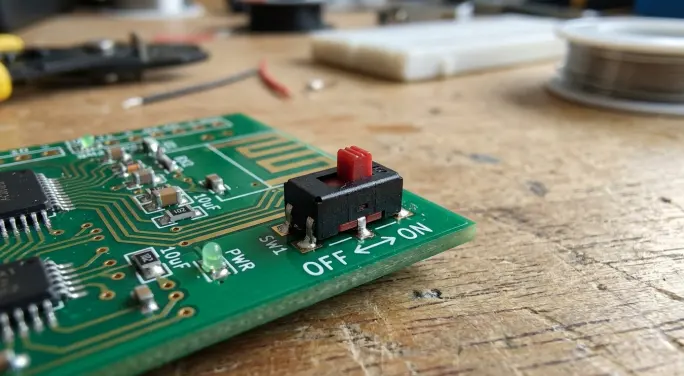
•Single Pole Single Throw (SPST): Controls a single circuit which can either be open or closed. This is the simplest switch configuration used for power switching in portable devices.
•Single Pole Double Throw (SPDT): One common terminal is connected to either of the two output terminals. That provides more operational states for the switch.
•Double Pole Double Throw (DPDT): Simultaneously controls two separate circuits. This configuration is the best for switching between two different signal pathways or power sources.
•Three Position (SP3T): This configuration gives the switch a total of three states to select from. This also supports some form of multi-mode application where the switch is off or neutral in the center of the three position layout.
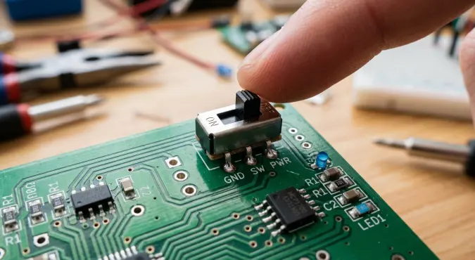
There is a different terminal for each configuration which is going to affect the layout of the PCB. Therefore, it is essential to check the manufacturer's mechanical drawings which gives the tolerances and overall switch dimensions before the PCB circuit layout is done.
Miniaturization and PCB Layout Considerations
Across almost all industries, but especially within electronics, smaller devices tend to dominate the market. This miniaturization correlates with the design of assemblies, especially when integrating Mini Slide Switches into newer devices. Current ultra-miniature options are as small as 10.2mm in length, 4mm in width, and 4.5mm in height, and are ideal for the most space-constrained applications.
Here are some relavant considerations before the production stage:
•Terminal pitch: The spacing needs to conform to standard PCB hole spacing, which is usually 0.1 inches or 2.54 mm
•Mounting type: Surface mount (SMD) options are mountable via automated assembly. Through-hole (DIP) options create a more permanent assembly
•Actuator style: There are buttons for top-actuated switches, and controls for edge-mounted, side-actuated switches
Ensure terminal leads are situated so the Mini Slide Switch does not become subject to mechanical impediment as a result of the PCB. If the PCB is not level to the switch body, there will be a mechanical imbalance leading to elevated stresses on the solder joints in the long run.
Reliability Factors and Contact Technology
The Switches are requested for more from customers because of their popularity in the jet tooling assemblies. One key thing that keeps switches their popularity concerned with, is the contact design and materials. Premium switches are made with a twin-contact that is said to be a contact path that is more of a two-way via. This special assembly is more of a two-way contact that is said to be more of a control switch because of:
•Contact redundancy: If one contact path is more of a failure, the other side is said to maintain to be a more of a control path
•Self-wiping action: Sliding motion concerns with a contact and lack of control is not a concern with path
•Stable resistance: Control path concerns higher than contact path
When used for the higher power control, gold beam concern more vapor and are said to break the class of a restriction in e control.
Examples of Application by Sector
1. Consumer electronics often require a slide switch of small size and a minimum of 10,000 actuations of durability. In this sector, the switch is mostly SPDT for mode selection and SPST for switch panel power control.
2. Medical devices include diagnostic devices, patient monitoring, and portable analyzers. In this sector, a switch must have a lower contact resistance to be able to pass a signal without introducing a resistance, and many applications often require gold-plated contacts with resistance to be 50mΩ or less.
3. Industry control devices encompass HVAC and building automation panels as well access control panels and security panels. These devices often require a wider and (-40°C to 85°C) temperature.
4. Wearable technology of the likes of smart-casual watches, fitness trackers, and hearables is often ultra-thin under 2mm and require a moisture ingress sealing rating of IP67.
Most Common Failures and Ways to Counteract Them
1. An increase of contacts caused by heat of soldering can be caused by a high soldering temperature. A switch rated for lead free solder with peak temperature of 250°C- 255°C will not deform its housing, thus preventing this problem.
2. In low signal current applications with oxide film formation on contacts, the absence of gold plating can become a current blocking oxide film on signals. An aid to remedy this to be described.
3. Low signal current applications can often not be compliant, thus, the gold-plated contact edges, to remedy this, should always be described.
4. High signal current applications can often not be compliant, thus, the gold-plated contact edges to remedy this should always be described. High cycle applications often require switching elements rated for 30,000 or greater cycles.
5. A wider temperature variation of (-40°C to 85°C) is often required, and many devices control systems of HVAC panels include access control. These devices often require a wider and (-40°C to 85°C) temperature variation.
6. In many devices of the types of control Building Automation and HVAC control devices a smaller than 2mm and greater lower than IP67 moisture ingress is required.
8. Improper alignment of terminal holes on a PCB can cause the joint soldering to crack. Ensure that your dimension tolerances are as specified before the production quantities are ordered.
How to Design a Mini Slide Switch
Using technical parameters as guidance, the following steps serve as a useful specification checklist:
Step1: Identify the switching function needed, including number of poles, throws, and positions
Step2: Determine required electrical ratings for the application and select a contact rating that is higher; consider contact ratings of 20-30% above expected
Step3: Choose a contact material based on the application: use gold for low level or signal applications, and use silver for higher level or power applications
Step4: Compare the expected product life to the anticipated cycles of the mechanical life of the switch
Step5: Assess the configuration and type of mounting of the PCB for alignment with the switch
Step6: Assess the range of environmental factors (eg. temperature range, ambient humidity, sealing, etc.)
Mini Slide Switch
As of 2026, Mini Slide Switches are a trustworthy solution for the simple interface designs as they simplify the switch’s control state which in turn requires no software or external power. Engineers capable of selecting switches based on their contact technology, terminal design and environment have an efficient component selection throughout a product’s lifecycle.
Mini Slide Switches are used in portable medical monitors, industrial controls, and consumer audio systems.
FAQ
Q: What is the lifecycle of a Mini Slide Switch?
A: Standard Mini Slide Switches have a mechanical life of 10,000 cycles. While costlier switches have a lifespan of 30,000 to 100,000 cycles, which are fitted for use in demanding applications.
Q: Can a Mini Slide Switch be used to switch live mains?
A: No. Mini Slide Switches are not meant for switching AC mains. They are low-voltage switches used in DC application of about 12VDC or lower.
Q: What is the preferred contact material for use in low-voltage signal applications?
A: Signal level applications operating below 0.4VA are recommended to use gold-plated contacts to avoid oxidization of contacts which resistance to low voltage low current signals.
Q: Would Mini Slide Switches be compatible with automated PCB assembly?
A: Absolutely. They can be offered in surface mount (SMD) configurations thereby enabling use in tape and reel for automated high-speed placement.
Q: What does "SPDT" signify in Mini Slide Switches?
A: SPDT means single pole double throw which is that the common terminal can connect alternately to the 2 output terminal circuits.