LED Tactile Switch Options: Colors, Mounting & Applications
When you need a push button that does more than register a press — one that communicates status, confirms activation, or guides an operator visually — a standard tact switch is no longer enough. An LED tactile switch integrates illumination directly into the switch body, giving you both a functional input and a live visual indicator in a single compact component.
The real challenge is not finding an LED tactile switch. It is choosing the right one. LED color, mounting configuration, electrical compatibility, and intended application all affect whether a switch performs exactly as designed or creates problems down the line. This guide covers every configuration dimension in practical detail so you can specify or source the right LED tactile switch with confidence.
What Is an LED Tactile Switch?
An LED tactile switch is a momentary push button switch with a built-in LED light source housed inside or immediately beneath the switch cap. When pressed, it provides the same crisp tactile feedback as a standard tact switch — a physical click or bump sensation that confirms actuation — while the LED independently or conditionally illuminates to signal operational state.
The switch body contains two functional circuits: the switching contact circuit (normally open, closed on press) and the LED illumination circuit (driven by a separate power path). These two circuits share the same footprint, which makes LED tact switches a space-efficient solution for any interface that requires both input and visual feedback.
For a complete overview of tact switch types, operating principles, and selection criteria across the full product family, refer to the complete tact switch guide.
LED Color Options for Tactile Switches
LED color is not a cosmetic decision. In control panels, instrumentation, and electronic interfaces, color carries meaning. Choosing the wrong color creates user confusion and can lead to operational errors in professional environments. Here is a breakdown of every illumination type available in LED tactile switches.
Single-Color LED Options
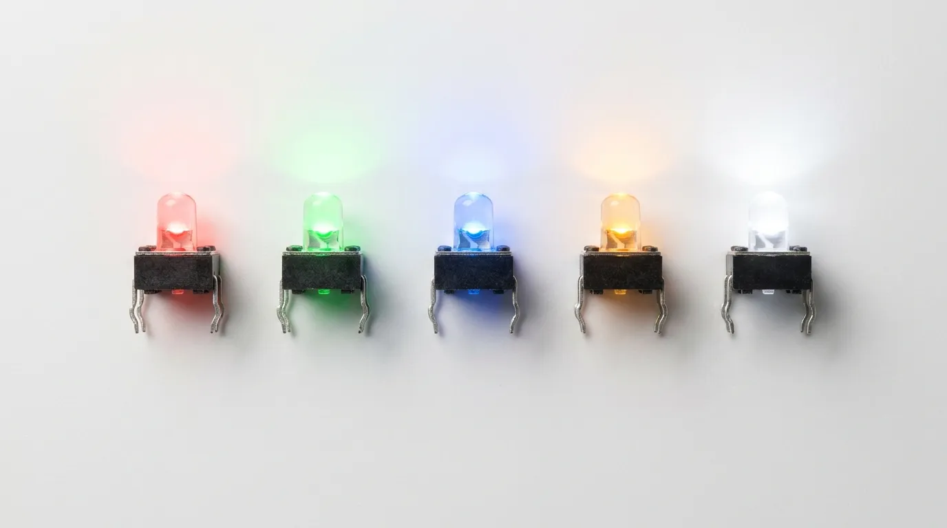
Single-color LED tact switches are the most widely used configuration. They are available in five standard LED colors, each with established conventional meanings in electronics and industrial interface design.
| LED Color | Conventional Meaning | Typical Use Case |
|---|---|---|
| Red | Alert, fault, power-off, stop | Error indicators, emergency stop confirmation, power-down buttons |
| Green | Active, running, OK, safe | Power-on buttons, system-ready indicators, start controls |
| Blue | Standby, power, information | Standby mode, connectivity status, menu navigation buttons |
| Amber / Yellow | Warning, caution, transitioning | Warm-up state, battery low, mode-switching indicators |
| White | General illumination, neutral status | Backlighting, keyboards, neutral-state touch interfaces |
Red and green remain the most common choices because they map directly to universal "stop/go" conventions used in electrical safety standards, making interfaces immediately intuitive for operators. Blue has become increasingly common in consumer electronics and networking equipment, where its association with standby and connectivity status is now well established.
Bi-Color LED Options
A bi-color LED tact switch contains two LED elements — typically one red and one green — within a single switch body. The illumination circuit can drive either color independently, allowing the same physical button to display different colors depending on the state of the connected system.
The most common bi-color pairings are:
- Red-Green — the standard for status indicators (fault vs. active)
- Red-Blue — used where standby/power-on distinction is needed
- Red-White — common in medical and consumer applications requiring neutral illumination in the default state
Bi-color LED tact switches are wired with a common anode or common cathode configuration. Understanding which configuration your circuit uses is essential before ordering, as the pin assignment differs between the two. A bi-color switch eliminates the need for two separate buttons on a panel — the same actuator signals both operational states through color change alone.
RGB LED Tactile Switches
RGB LED tact switches integrate red, green, and blue LED elements in one package, allowing the illumination circuit to produce virtually any color through PWM mixing. These are the highest-specification illumination option and are typically used in:
- Advanced human-machine interfaces (HMI) where a single button must represent multiple states
- Programmable control panels with dynamic color assignment
- Consumer electronics with customizable backlight themes
- Embedded systems where LED color is driven directly by firmware logic
RGB tact switches require three separate LED control lines plus a common connection, which adds routing complexity on the PCB. For most industrial or medical applications, single-color or bi-color switches are simpler, more reliable, and easier to qualify. RGB configurations are best suited to designs where software-driven color logic is already built into the product architecture.
Mounting Styles for LED Tactile Switches

Mounting style determines how the LED tact switch attaches to the PCB or panel, how it is assembled, and what constraints it places on board height and footprint. There are four main mounting configurations, and each has specific applications where it clearly outperforms the others.
SMD (Surface Mount) LED Tactile Switches
Surface mount LED tact switches are designed for automated PCB assembly using reflow soldering. The switch sits flat on the PCB surface with no pins passing through the board, which reduces board height and suits high-volume production lines where manual soldering is not viable.
SMD LED tact switches typically have a lower profile compared to their through-hole counterparts — some series reach a total height of 2.0mm or less — making them the natural choice for compact wearable electronics, slim handheld devices, and high-density PCB layouts where vertical space is constrained. The LED illumination circuit is integrated into the same SMD footprint, and termination is typically via SMD tabs or gull wing contacts.
For designs where board height is the primary constraint, also review low-profile tact switch options — some low-profile variants are available with LED illumination in sub-2mm total heights.
Best for: Automated PCB assembly, compact consumer electronics, wearables, high-density boards.
THT (Through-Hole) LED Tactile Switches
Through-hole LED tact switches have PC pin terminations that pass through drilled holes in the PCB and are soldered on the underside. This provides a stronger mechanical bond than surface mount pads, which makes THT variants more resistant to mechanical stress — important in products that are handled frequently or subject to vibration.
THT LED tact switches are available in a wide range of cap styles, sizes, and colors, often with bezel options for panel-style integration. They are generally taller than SMD variants, typically ranging from 5mm to over 10mm in total height depending on the cap selected. Operating forces range from approximately 100gf to 350gf across product series, and cycle life ratings commonly reach 500,000 to 1,000,000 actuations in quality components.
Best for: Hand-assembled prototypes, products requiring strong mechanical anchoring, industrial panels, designs with relaxed height constraints.
Right-Angle LED Tactile Switches
Right-angle (horizontal) LED tact switches orient the actuation axis parallel to the PCB surface rather than perpendicular to it. The switch is mounted upright on the PCB edge, and the actuator faces outward — allowing the button to be pressed from the side rather than from the top.
This mounting style is used when a product's mechanical design requires buttons to be accessed from the edge of a board, the side of an enclosure, or through a slot in a housing wall. It also reduces the overall height profile of the button relative to the board surface, which is valuable when enclosure depth is limited. LED tact switches in right-angle configuration are available in both THT and SMD versions.
For a thorough look at right-angle mounting design considerations, see the dedicated right-angle tact switch guide.
Best for: Edge-actuated interfaces, enclosures with side-access buttons, space-constrained product housings.
Panel Mount LED Tactile Switches (With Wire Leads)
Panel mount LED tact switches use a separate PCB module that is mounted behind the panel, with the switch actuator passing through a cutout in the front panel surface. Four wire leads connect the switch and LED circuits back to the main PCB. Standard panel cutout diameters are typically 16mm, and connectors are usually 2.54mm pitch.
This configuration is chosen when the switch must be accessible on a front panel while the electronics sit recessed inside an enclosure. It allows IP-rated sealing around the panel opening, with some variants achieving IP67 protection against dust and water ingress. Panel mount LED tact switches are commonly specified for custom control boxes, medical instruments, and industrial equipment where the panel finish and button placement are design-driven rather than PCB-driven.
Best for: Front-panel interfaces, enclosures requiring IP-rated sealing, medical instruments, custom industrial control boxes.
Key Electrical Specifications to Understand
An LED tact switch has two independent electrical circuits inside one body. Getting the switching contact specs right is standard practice — but the LED circuit specs require equal attention and are more frequently overlooked during the design phase.
| Parameter | Typical Range | Why It Matters |
|---|---|---|
| LED Forward Voltage (Vf) | ~2.0V (red, green, amber) / ~3.0–3.3V (blue, white, RGB) | Determines compatibility with your supply voltage and resistor calculation |
| LED Forward Current (If) | 5mA – 20mA (typical) | MCU GPIO pins commonly source 8–20mA maximum — exceeding this damages the GPIO |
| Luminous Intensity | 5mcd – 100mcd+ (varies by color and series) | Determines LED visibility in ambient lighting conditions |
| Switch Contact Rating | Typically 50mA at 12VDC | Ensures the contact circuit handles the load without degrading |
| Operating Force | 100gf – 350gf | Affects tactile feel and accidental actuation risk |
| Electrical Life (Cycle Life) | 100,000 – 1,000,000 cycles | Defines product lifespan under expected actuation frequency |
| Operating Temperature | -40°C to +85°C (typical) | Confirms suitability for the deployment environment |
| IP Rating (sealed variants) | IP67 (select panel mount and SMD series) | Needed for washdown, outdoor, or splash-resistant environments |
The forward voltage difference between LED colors is the most commonly misunderstood specification. A red LED tact switch typically requires ~2.0V forward voltage, while a blue or white LED requires ~3.0–3.3V. If your design runs on a 3.3V supply rail and you add a blue LED tact switch without accounting for the forward voltage drop and resistor, the LED may not illuminate reliably or may draw excessive current. Always calculate the current-limiting resistor value based on the specific LED color's Vf, not a generic assumption.
Applications by Industry

LED tactile switches appear across nearly every electronics-intensive industry, but the configuration requirements vary significantly between sectors.
| Industry | Preferred LED Color | Mounting Type | IP Rating Need | Notes |
|---|---|---|---|---|
| Industrial Control | Red / Green / Amber | THT or Panel Mount | IP67 for harsh areas | Status confirmation, safety interlock panels |
| Automotive | Blue / White / Amber | SMD or Right-Angle | Optional | Dashboard controls, steering wheel buttons, HVAC interfaces |
| Medical Devices | Green / Red / Bi-color | SMD or Panel Mount | IP54–IP67 | Diagnostic instruments, portable monitors, infusion pumps |
| Consumer Electronics | White / RGB | SMD | Not typically required | Power buttons, keypads, gaming controllers |
| Networking / Telecom | Green / Blue | SMD or THT | Optional | Port status buttons, server rack interfaces, data center equipment |
| IoT / Embedded Systems | RGB or single-color | SMD | Optional | Programmable status buttons, device pairing, mode selection |
In industrial control panels, the color convention follows IEC and machine safety standards: green indicates a running or safe state, red indicates a fault or stop condition, and amber signals a transitional or warning state. Using red where green is expected — or vice versa — creates a real safety risk in operator interfaces, not just a cosmetic inconsistency.
Medical and diagnostic equipment frequently uses bi-color (red-green) LED tact switches, where the color change signals operational state transitions — for example, green during normal operation and red during an alarm or fault condition — all through the same physical button. This reduces panel complexity without sacrificing status clarity.
How to Choose the Right LED Tactile Switch
The right LED tactile switch for your design depends on six factors evaluated in sequence. Skipping any of them tends to create rework at the prototype or production stage.
1. Define the application environment.
Is the switch inside a sealed enclosure, exposed to moisture, vibration, or extreme temperatures? Harsh environments require THT for mechanical strength or sealed panel mount with IP67 rating. Standard consumer and office electronics can use SMD without additional protection.
2. Choose the LED color based on function, not aesthetics.
Map the color to its conventional meaning within your industry. If the button indicates power-on, green is the established convention. If it signals a fault or requires operator attention, use red or amber. Reserve RGB for designs where dynamic color changes are driven by firmware logic.
3. Select the mounting type based on PCB layout constraints.
If board height is critical, SMD or right-angle mount are the correct directions. If mechanical durability and hand-soldering are priorities, THT is the better choice. If the button must appear on a front panel surface, panel mount with wire leads is the only practical option.
4. Confirm electrical compatibility.
Check the LED's forward voltage against your supply rail. Calculate the current-limiting resistor. Confirm that the GPIO or driver circuit can supply the required forward current without exceeding its source current limit. This step prevents LED failure and protects the driving circuit.
5. Check IP rating requirements.
If the product will be cleaned, used in wet environments, or exposed to dust ingress, identify the required IP rating and select a variant that meets it — not one that approximates it.
6. Evaluate customization needs.
Custom cap colors, engraved legends (power symbol, ring illumination), bezel styles, or non-standard LED colors may require a custom order with minimum order quantities. Identify these requirements early to avoid delays.
For readers comparing LED tact switches against other illuminated switch types — including backlit pushbuttons and panel indicators — the illuminated tact switch guide covers the broader illuminated switch family in detail.
If you are still evaluating whether an illuminated variant is the right choice for your design versus a standard tact switch, the full range of tact switches covers all types and application scenarios.
Common Mistakes When Specifying LED Tactile Switches
| Mistake | Why It Happens | How to Avoid It |
|---|---|---|
| Assuming all LED colors have the same forward voltage | Engineers apply a generic 2V Vf to all colors | Always check the datasheet for the specific LED color — blue/white/RGB require ~3.0–3.3V Vf |
| Driving the LED directly from a GPIO without a current-limiting resistor | Overlooking the LED as a separate circuit | Add a series resistor calculated from: R = (Vsupply – Vf) / If |
| Reversing LED polarity during assembly | LED pins are not always clearly marked on the PCB silkscreen | Mark LED anode/cathode clearly on the PCB; verify with datasheet pin diagram before soldering |
| Selecting THT in a high-vibration application without strain relief | THT is assumed to be mechanically superior in all cases | In high-vibration environments, SMD with proper adhesive underfill or right-angle mount with housing support performs better |
| Ignoring PCB height when specifying THT variants | THT LED tact switches are taller and may collide with enclosure lid | Verify the total height (switch body + cap) against the enclosure internal clearance before committing to a footprint |
| Choosing the wrong IP rating for the environment | Assuming a standard switch tolerates occasional splashing | IP20 or unrated switches fail in washdown or outdoor environments — verify IP class against the use environment |
| Specifying a bi-color switch without confirming common anode/cathode | Two wiring configurations exist; assuming both are the same | Confirm whether the switch is common anode or common cathode and match it to the LED driver circuit design |
Frequently Asked Questions
What colors do LED tactile switches come in?
LED tactile switches are available in five standard single colors — red, green, blue, yellow/amber, and white. Bi-color options (most commonly red-green, red-blue, and red-white) allow two colors within one switch body. Full RGB variants provide access to any color through PWM-driven mixing of red, green, and blue elements.
What is the difference between an SMD and THT LED tactile switch?
SMD (surface mount) LED tact switches are designed for reflow soldering, sit flat on the PCB surface, and offer a lower profile suitable for automated assembly. THT (through-hole) versions use PC pins that pass through the PCB, providing stronger mechanical anchoring and are more suitable for hand-soldered prototypes and vibration-prone applications.
What does the LED color in a tactile switch indicate?
LED color follows established conventions in electronics and machine safety: red typically signals a fault, alert, or stop condition; green indicates active or normal operation; blue is used for standby or power status; and amber signals a warning or transitional state. These conventions are especially important in industrial and medical applications where color directly supports operator safety.
What forward voltage does an LED tactile switch require?
Red, green, and amber LEDs in tact switches typically require a forward voltage (Vf) of approximately 2.0V. Blue, white, and RGB LEDs require approximately 3.0–3.3V Vf. The difference matters when designing the current-limiting resistor for the LED drive circuit, particularly in 3.3V MCU-based systems.
What is a bi-color LED tactile switch?
A bi-color LED tact switch contains two LED elements in one switch body, allowing it to display either of two colors depending on which LED circuit is activated. The red-green combination is the most common and is used in status panels where a single button must signal both active (green) and fault (red) states. Bi-color switches are wired with either a common anode or common cathode, which must match the LED driver circuit design.
Can LED tactile switches be used in industrial or outdoor environments?
Yes. Sealed variants with IP67 ratings are available in both THT panel mount and select SMD configurations. These protect against dust ingress and temporary water immersion, making them suitable for industrial control panels, outdoor enclosures, and equipment subject to cleaning or splash exposure.
Do LED tactile switches need an external resistor?
In most circuits, yes. The LED inside the switch requires a current-limiting resistor in series with the LED circuit. Without it, the LED draws uncontrolled current, which can destroy the LED, damage the driving GPIO, or create unreliable behavior. The resistor value is calculated using: R = (supply voltage – LED forward voltage) ÷ LED forward current.
Related Guides
LED tactile switches are one part of a larger family of illuminated and non-illuminated tact switch configurations. If your design requirements lead you beyond single-color PCB-mounted LED variants, the following resources cover related topics in depth.
For designs where the switch actuator must face the board edge or a housing wall, the right-angle tact switch guide covers horizontal mounting configurations, PCB footprints, and enclosure integration in detail.
If your design requires the lowest possible board height — particularly in slim wearables, portable devices, or high-density boards — the low-profile tact switch guide covers sub-3mm and ultra-low-profile options, some of which are also available with LED illumination.
For a broader comparison of illuminated switch types beyond tact switches — including illuminated pushbuttons, panel indicators, and backlit switch arrays — the illuminated tact switch guide provides a wider reference point.
And if you are still at the stage of evaluating which type of tact switch is right for your application altogether, the complete tact switch overview covers the full product category with selection guidance across all types.
Conclusion
An LED tactile switch is a precise, functional component — and specifying it correctly requires more than picking a color that looks right. The LED color carries operational meaning, the mounting type determines assembly compatibility and mechanical performance, the electrical parameters define circuit design requirements, and the IP rating defines where the switch can be reliably deployed.
For most standard PCB designs, SMD or THT single-color LED tact switches cover the majority of requirements. Bi-color variants are the smart choice wherever a single button must signal two system states. Panel mount configurations solve front-panel integration challenges. And RGB switches are best reserved for designs where the firmware is already managing dynamic color output.
If you are working through configuration decisions for a specific product and need technical support, contact the HX Switch team directly to discuss your application requirements and request samples.