Illuminated Tact Switch: LED Feedback for Control Panels
When operators work with control panels — especially in low-light environments, dense machine interfaces, or safety-critical systems — a mechanical click alone is not enough. They need to see which button was pressed, what state the system is in, and whether their input was registered. That is exactly the problem an illuminated tact switch solves.
An illuminated tact switch combines two functions in a single, compact component: tactile actuation and LED status feedback. Instead of wiring a separate indicator LED next to every button, the light source is integrated directly into the switch body. The result is a cleaner panel layout, faster operator response, and fewer discrete components on the board.
This guide covers how illuminated tact switches work, what types are available, which specifications matter for control panel integration, and how to choose the right one for your application. For a full overview of the tact switch category, including all types and general selection criteria, see our complete tact switch guide.
What Is an Illuminated Tact Switch?
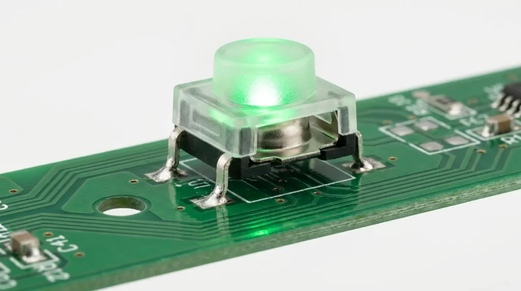
An illuminated tact switch is a momentary tactile switch with a built-in LED that provides visual feedback alongside the physical press. When the user presses the actuator, the switch briefly closes an electrical circuit. The integrated LED — controlled through its own separate circuit — illuminates to indicate switch status, panel state, or system condition.
In simple terms, it is a standard tact switch with one critical addition: an LED circuit built into the same housing, independently controlled from the switch contact. This distinction matters enormously for wiring and design, as explained in the next section.
Illuminated tact switches are widely used in industrial control panels, HMI interfaces, medical device enclosures, test and measurement equipment, and front-panel button arrays — anywhere a button must both actuate a function and communicate a system state at a glance.
How the LED Feedback Mechanism Works
Switch Contact vs. LED Circuit: Why They Are Separate
This is the most important concept to understand before designing with or specifying illuminated tact switches — and the detail that most generic product descriptions skip entirely.
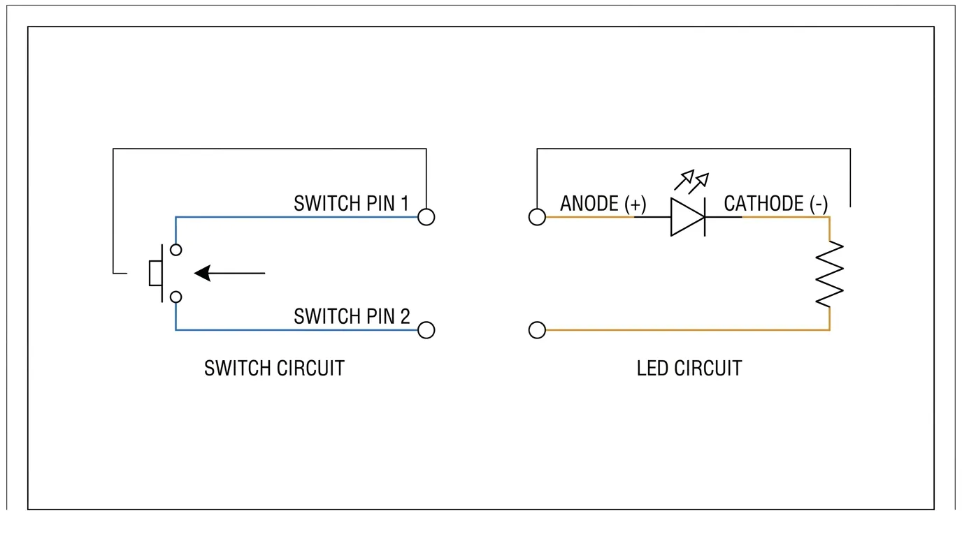
In a standard tact switch, pressing the actuator collapses a metal dome contact, momentarily closing the circuit between two pins. That is the only function. In an illuminated tact switch, the LED operates on a completely independent circuit with its own dedicated pins, its own voltage, and its own current path.
Physically, this means the switch typically has more pins than a standard tact switch. Where a basic tact switch has 4 pins organized as 2 pairs, an illuminated version adds 2 additional LED pins (anode and cathode), bringing the total to 6 in a common through-hole configuration. Some SMD variants use different footprints, so always verify pin count in the datasheet before designing a PCB layout.
Because the circuits are independent, the LED can be driven in several modes depending on your system logic:
- LED always on — the LED is connected directly to power, independent of whether the button is pressed. Useful for backlit panels or identifying button positions in dark environments.
- LED on when pressed — the LED illuminates only during active button press, giving instant press confirmation.
- LED controlled by system logic — the LED is driven by a microcontroller or PLC output, showing system state regardless of button press activity. This is the most common mode in industrial panels.
The forward voltage of the LED (typically 1.8V–3.5V depending on color) and the supply voltage of your panel will determine whether a current-limiting resistor is required. Many illuminated tact switches, particularly panel mount versions, include a built-in resistor pre-configured for 5V, 12V, or 24V operation. If yours does not, a resistor is mandatory — without it, the LED will burn out quickly from overcurrent.
Types of Illuminated Tact Switches
By LED Color: Single, Bi-Color, and RGB
The most common option is a single-color LED tact switch, available in red, green, blue, yellow, and white. These suit most straightforward panel applications where each button has a fixed status meaning — for example, a green button for start and a red button for stop.
Bi-color LED tact switches contain two separate LEDs within a single switch body, each on independent lines. By switching which LED is active, the same button can display two different colors — most commonly red and green. This is highly useful in industrial panels where a single button must indicate two states: active (green) vs. fault (red), or enabled vs. disabled, without requiring two separate switch positions.
RGB illuminated tact switches support full multi-color control via a common anode/cathode plus three separate color channels. They are used in applications where color-coded feedback must be dynamically changed in firmware — such as mode selectors in test equipment, gaming peripherals, or advanced HMI interfaces.
By Mounting Method: SMD, THT, and Panel Mount
Through-hole (THT) illuminated tact switches are the most common choice for control panel PCBs. They offer secure mechanical anchoring, are easier to hand-solder during prototyping, and are available in the widest range of LED colors and cap options. Typical operating specs for a quality THT illuminated tact switch are 50mA at 12VDC with 500,000 cycles of rated life.
SMD (Surface Mount Device) illuminated tact switches are designed for automated PCB assembly, offering a smaller footprint and lower profile. They suit compact HMI boards and embedded panels where board space is limited. If your design prioritizes compact board height, see our guide to low-profile SMD tact switches for mounting-specific guidance.
Panel mount illuminated tact switches are assembled into a bezel module and installed through a front-panel cutout. Unlike PCB-mounted variants, the switch actuator is flush with or proud of the panel face, accessible to an operator without opening the enclosure. These are the most common choice for machine front panels, industrial operator interfaces, and rack-mounted control systems. They typically include a built-in resistor for direct 12V or 24V panel supply compatibility.
For designs where the switch must be accessed from the side of a PCB — such as in enclosures where the PCB mounts parallel to the panel face — a right-angle illuminated tact switch is the appropriate solution. You can find detailed mounting guidance in our right-angle tact switch guide.
Key Specifications for Control Panel Applications
Not all datasheets present illuminated tact switch specifications consistently. The following are the critical values to verify before specifying a switch for a control panel design.
Electrical Ratings
| Specification | Typical Value | Why It Matters |
|---|---|---|
| Switch contact rating | 50mA at 12VDC (SPST-NO) | Defines the signal load the switch contact can handle |
| LED forward voltage (Vf) | 1.8V–3.5V (varies by color) | Determines resistor calculation for your supply voltage |
| LED forward current | 10mA–30mA | Sets maximum continuous LED drive current; exceed it and the LED fails |
| Built-in resistor options | 5V / 12V / 24V (some series) | Eliminates need for external resistor on standard supply voltages |
| Pin configuration | 6-pin (4 switch + 2 LED) typical | Must match your PCB footprint or bezel connector |
Mechanical and Environmental Ratings
| Specification | Typical Value | Why It Matters |
|---|---|---|
| Operating life | 100,000–500,000 cycles | Industrial panels require high-cycle switches for continuous shift use |
| Actuation force | 160gf–200gf typical | Lower force causes accidental activation; higher force reduces operator comfort |
| Contact resistance | 100mΩ max (initial) | Low contact resistance ensures clean signal transmission |
| Operating temperature | −20°C to +70°C | Confirms suitability for ambient panel environments |
| IP rating | IP40–IP67 depending on series | Sealed variants needed for panels exposed to dust, oil mist, or wash-down |
Always verify that the LED specification and the switch contact specification are listed separately in the datasheet. If a supplier provides only a single combined voltage or current rating without distinguishing between the switch circuit and LED circuit, request clarification before placing a production order.
LED Color Coding in Industrial Control Panels
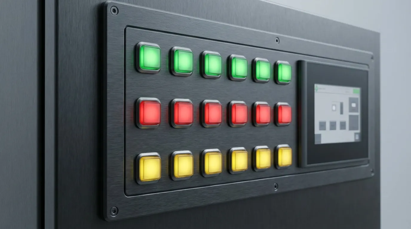
In industrial and HMI panel design, LED color is not just an aesthetic choice — it carries functional meaning. Most control panel environments follow established color conventions that operators are trained to recognize immediately. Using the wrong LED color on a critical button introduces ambiguity and can contribute to operator error.
| LED Color | Standard Panel Meaning | Common Application |
|---|---|---|
| Green | Running, ready, OK, confirmed | Start button, system-active indicator, process confirmed |
| Red | Fault, alarm, emergency stop, off | Fault acknowledgement, E-stop, alarm reset button |
| Yellow / Amber | Caution, standby, in-progress | Warning state, transition mode, pending status |
| Blue | Information, specific mode active | Mode selector, maintenance mode, filter/select |
| White | Neutral, illumination, unlabeled | Backlit panel buttons, non-status buttons |
A bi-color red-green illuminated tact switch is particularly efficient in this context — it allows a single button position to communicate both the active state (green) and the fault state (red) without occupying two separate panel locations. This is common in motor start/stop controls, valve position buttons, and alarm acknowledgement panels.
How to Select the Right Illuminated Tact Switch for Your Panel
The right illuminated tact switch for your application depends on five design parameters that should be determined before reviewing any product catalog.
1. Panel supply voltage. Determine whether your control panel operates at 5V, 12V, or 24VDC. Match this to the LED-rated voltage of the switch series, or confirm you will be adding an external current-limiting resistor calculated for your supply. Using a 5V-rated switch LED on a 24V supply without a resistor will destroy the LED.
2. Required LED color or color mode. For simple on/off status applications, a single-color LED is sufficient. If a button must display two states — enabled vs. faulted, for instance — specify a bi-color variant. For firmware-driven multi-color feedback, choose an RGB illuminated tact switch with separate color control pins.
3. Mounting method. If the switch is PCB-mounted and placed on a board inside an enclosure, choose SMD or THT. If the switch must be accessible on the front face of a panel or enclosure, choose a panel mount variant with bezel. Confirm the bezel diameter or panel cutout dimension before ordering.
4. Operating life requirement. For light-use applications, 100,000 cycles is adequate. For industrial panels with frequent operator interaction — such as production line controls used across three-shift operations — specify a switch series rated for 300,000 cycles or more.
5. Environmental conditions. Standard illuminated tact switches without IP sealing are appropriate for enclosed, dry panel environments. For panels exposed to coolant mist, washdown, or high particulate environments, specify a sealed variant with at minimum IP65 protection.
The table below summarizes the selection logic:
| Design Requirement | Recommended Switch Type |
|---|---|
| 12V or 24V industrial panel, single status color | THT single-color, built-in resistor for your supply voltage |
| Two-state visual feedback on one button position | Bi-color LED tact switch (red-green) |
| Compact PCB, automated assembly | SMD illuminated tact switch |
| Front-panel operator access, external enclosure | Panel mount with bezel, IP-rated if needed |
| Firmware-controlled multi-color status | RGB illuminated tact switch |
| Side-entry PCB orientation | Right-angle illuminated tact switch |
Common Control Panel Applications
Illuminated tact switches are used wherever a control interface requires both physical input and clear visual feedback in a compact form factor.
Industrial automation panels are the primary application. Reset buttons, alarm acknowledgement buttons, mode selectors, and emergency function controls all benefit from LED feedback that tells the operator what the current machine state is — not just that the button was pressed. A green-illuminated start button confirms the system is running; a red illuminated fault button tells the operator an alarm is active and awaiting acknowledgement.
HMI and SCADA front panels use illuminated tact switches extensively on rack-mounted displays, operator workstations, and machine-side control boxes. The switches provide tactile confirmation for operators who may be wearing gloves or working in poor lighting conditions, while the LED feedback reduces the chance of a mispress going unnoticed.
Medical device interfaces require illuminated tact switches where reliability and unambiguous status feedback are mandatory. Buttons on diagnostic equipment, infusion pump panels, and surgical instrument interfaces use LED feedback to confirm that an input has been registered — reducing the risk of a critical action being performed twice or not at all.
Test and measurement equipment commonly uses RGB or multi-color illuminated tact switches on front panels, where button function changes depending on operating mode, and the LED color communicates the active mode to the technician directly on the button itself.
Common Mistakes to Avoid
| Mistake | Root Cause | How to Avoid |
|---|---|---|
| LED burns out immediately after installation | No current-limiting resistor, or supply voltage applied directly to LED without resistor | Always check if the switch has a built-in resistor; if not, calculate and add an external one for your supply voltage |
| LED does not illuminate at all | Reverse LED polarity on wiring | Confirm anode (+) and cathode (−) pin positions in the datasheet before soldering or connecting |
| Switch footprint does not match PCB | Specifying an illuminated variant without checking pin count (6-pin vs 4-pin footprint) | Verify the exact pin configuration of the illuminated switch — it will differ from a standard tact switch footprint |
| LED voltage spec confused with switch contact voltage | Treating the single listed voltage as applying to both circuits | Always check that the datasheet lists LED voltage and switch contact voltage separately |
| LED too dim for bright environment | Using a standard-brightness LED switch in a high-ambient-light panel | Specify a high-brightness LED variant, or consider a larger-format panel mount switch with a cap diffuser |
| LED color does not match IEC/panel convention | Selecting LED color for aesthetics rather than function | Follow established industrial color conventions — green for active/OK, red for fault/alarm |
Related Guides
If your panel design requires switches that access buttons from a non-vertical orientation — for example, where the PCB mounts flat and the button must face outward from a chassis wall — the right-angle tact switch guide covers the mounting geometry and mechanical considerations for that specific configuration.
For applications where board height is constrained — compact HMI modules, embedded instruments, or miniaturized panels — review our low-profile SMD tact switch guide, which covers SMD illuminated variants in the context of space-critical designs.
For a full understanding of the tact switch family, including all types, general specifications, and application context across the entire category, visit our complete tact switch guide.
Frequently Asked Questions
What is an illuminated tact switch?
An illuminated tact switch is a momentary tactile switch with an integrated LED. Pressing the actuator closes the switch contact circuit to trigger a system action, while the built-in LED — operating on a separate, independent circuit — provides visual status feedback. The two circuits are electrically isolated from each other and controlled independently.
Is the LED circuit separate from the switch contact in an illuminated tact switch?
Yes. In virtually all illuminated tact switches, the LED and the switch contact are on completely independent circuits with separate pins. This means the LED can be driven by a microcontroller output or system logic signal, entirely separate from the switch signal being sent to the processor or PLC. Typical pin counts are 6 (4 for switch, 2 for LED) for through-hole variants.
What voltage do illuminated tact switches run on?
The switch contact typically handles low-level signal voltages (commonly 12VDC at 50mA). The LED side depends on the LED's forward voltage — usually 1.8V to 3.5V for standard LEDs. Many panel mount series include built-in resistors pre-configured for 5V, 12V, or 24V DC supply voltages, eliminating the need for an external resistor in standard industrial panel designs.
Can I use an illuminated tact switch on a 24V industrial panel?
Yes, provided you either select a variant with a built-in resistor rated for 24V, or calculate and add an external current-limiting resistor based on the LED's forward voltage and your required forward current. Never connect the 24V supply directly to the LED pins of a switch rated for 12V without a resistor — this will permanently damage the LED.
What LED colors are available for illuminated tact switches?
Standard single-color options include red, green, blue, yellow, and white. Bi-color variants typically offer red-green or red-blue combinations, with each color independently controlled. RGB illuminated tact switches provide full-color control via separate R, G, and B channels and are used where firmware needs to drive dynamic color changes.
What is the difference between an illuminated tact switch and an illuminated push button?
Both integrate an LED, but they differ in size, force, and application scale. Illuminated tact switches are compact, surface-mount or small through-hole components designed for PCB integration or lightweight panel interfaces, with actuation forces typically in the 160–200gf range. Illuminated push buttons are larger, panel-mount components built for heavier operator interaction, with higher operating forces and larger footprints intended for machine front panels.
What is the typical operating life of an illuminated tact switch?
Operating life varies by product series and quality grade. Standard commercial-grade illuminated tact switches are typically rated between 100,000 and 300,000 actuation cycles. Higher-grade industrial series can be rated up to 500,000 cycles for through-hole types, with some dome-contact sealed designs reaching significantly higher. Always verify the rated life in the datasheet against your expected actuation frequency in the application.
How do I know if my illuminated tact switch needs a current-limiting resistor?
Check the datasheet for a "built-in resistor" specification. If it lists pre-configured resistor values for 5V, 12V, or 24V, no external resistor is needed for those supply voltages. If no built-in resistor is mentioned, calculate the required resistance using the formula: R = (Vsupply − Vf) ÷ If, where Vf is the LED forward voltage and If is the desired forward current (typically 10–20mA for standard panel applications).
Choosing the Right Switch Starts with the Right Brief
An illuminated tact switch is a deceptively simple component with meaningful design depth. The LED and switch contact being electrically independent is not just a technical footnote — it is the foundation of how you wire it, how you control it, and how you match it to your panel supply voltage. Getting that wrong at the specification stage means a redesign at the PCB stage.
For most industrial control panel applications, the selection decision comes down to three factors: panel supply voltage (to confirm resistor compatibility), LED color or color mode (to match your status logic), and mounting method (PCB-mount THT or SMD vs. front-panel bezel). Once those three are locked, the remaining specifications — life cycles, contact resistance, IP rating — are straightforward to verify against your application requirements.
If you are sourcing illuminated tact switches for a control panel project and need guidance on the full range of available variants, contact our team or explore the complete tact switch product range to find the series that best matches your panel design requirements.
Prepared using Claude Sonnet 4.6 Thinking