DIP Tactile Switch Guide for Stable PCB Mounting
If you are designing a PCB that needs a push button with reliable mechanical grip, solid solder joints, and long-term durability under repeated use, a DIP tactile switch is one of the most dependable choices available. Engineers have relied on through-hole tact switches for decades — not out of habit, but because the physics of through-hole mounting genuinely outperforms surface mount in high-stress and hand-assembled applications.
This guide explains exactly what a DIP tactile switch is, how its through-hole construction delivers mounting stability, what specifications matter most for your project, and how to select the right one without second-guessing your design. Whether you are a PCB designer, prototype engineer, or procurement manager evaluating suppliers, this guide gives you everything you need before making a decision.
What Is a DIP Tactile Switch?
A DIP tactile switch — also called a through-hole tact switch or THT tact switch — is a momentary push-button switch designed to be mounted by inserting its metal pins through drilled holes in a PCB and soldering them on the underside. The term "DIP" refers to the Dual In-line Package format, a standard through-hole component layout where pins are arranged in two parallel rows.
In simple terms: you press the button, it completes a circuit for as long as you hold it, and it opens again the moment you release. There is no latching, no toggle — just a clean momentary contact. The tactile part refers to the spring dome inside the switch body that collapses under finger pressure and produces a physical click sensation and sometimes a faint audible snap, confirming the actuation to the user.
DIP tactile switches are part of the broader tact switch family, which also includes SMD and surface-mount variants. For a complete overview of all tact switch types, you can refer to the complete tact switch guide.
How a DIP Tactile Switch Works
The operating mechanism of a DIP tactile switch is simple and proven. Inside the switch body sits a curved metal spring dome positioned over two fixed contacts on the base. When the switch is at rest, the dome holds its arched shape, and the circuit between the two contacts is open — no current flows.
When you apply force to the actuator (the protruding button on top), the dome compresses downward. At a specific threshold — defined by the actuation force rating — the dome snaps inward and bridges the two fixed contacts, completing the circuit. The force required to trigger this snap is precise and consistent, which is what gives the switch its characteristic tactile feedback. The moment you release pressure, the dome springs back to its original arch and the circuit opens again.
Why 4 Pins Create Better PCB Stability
Most DIP tactile switches use a 4-pin configuration, even though electrically you only need 2 pins to operate the circuit. The extra two pins serve a purely mechanical function: they anchor the switch body to the PCB from two additional points, distributing stress across the board when the button is pressed repeatedly.
This matters more than it may seem. Every time a user presses a tactile switch, a downward and sometimes lateral force is applied to the switch body. Over thousands of cycles, this stress concentrates at the solder joints. With only 2 solder connections, that stress has nowhere to go except into those joints — eventually causing micro-cracks. With 4 pins soldered into 4 through-holes, the mechanical load is shared, and the switch remains firmly seated on the board far longer.
2-Pin vs 4-Pin vs 5-Pin DIP Configurations
| Configuration | Electrical Pins | Mechanical Pins | Best Use Case |
|---|---|---|---|
| 2-pin | 2 | 0 | Space-constrained designs, low-cycle applications |
| 4-pin | 2 | 2 | Standard general-purpose and industrial applications |
| 5-pin | 2 | 2 + 1 center | High-stability applications, compact packaging formats |
The 4-pin version is the industry standard for good reason — it balances routing simplicity with mounting strength. The 5-pin variant adds a center ground or reinforcement pin useful in vibration-prone environments. 2-pin switches exist but are better suited for low-cycle or space-critical applications where mechanical stress is minimal.
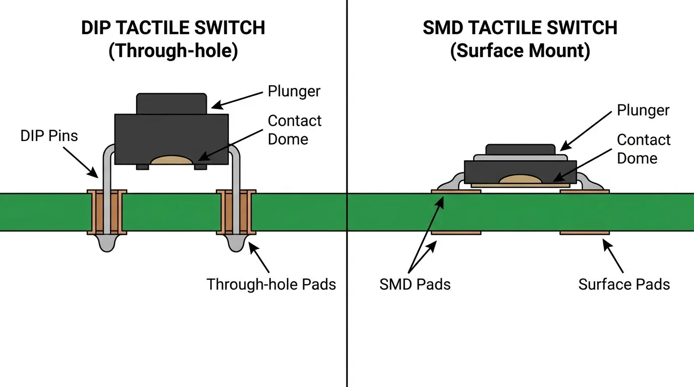
DIP Tactile Switch vs SMD Tactile Switch: Key Differences
The most common decision engineers face is whether to use a DIP (through-hole) or SMD (surface-mount) tactile switch. Both types use the same spring dome mechanism internally. The difference lies entirely in how they connect to the PCB — and that difference has significant downstream effects on stability, assembly, and repairability.
DIP switches insert through the board and solder on the bottom side, creating a physical anchor. SMD switches sit on the surface and solder only to the top pads, relying entirely on the solder pad bond for mechanical support. For a deeper look at surface-mount options, see the SMD tactile switch guide.
| Feature | DIP Tactile Switch | SMD Tactile Switch |
|---|---|---|
| Mounting method | Through-hole (pins through PCB) | Surface mount (pads on PCB surface) |
| Mechanical stability | High — pins anchor through board | Moderate — relies on pad solder bond |
| Assembly method | Hand soldering, wave soldering | Reflow soldering (pick-and-place) |
| Rework / replacement | Easy to desolder and replace | Requires hot air or reflow station |
| PCB board space | Requires drill holes, larger footprint | Smaller footprint, no drill holes needed |
| Best for | High-cycle, industrial, manual assembly, prototyping | High-volume automated PCB production |
| Component height | Taller (actuator above board) | Lower profile |
The main difference is this: DIP switches are the better choice when mechanical durability and ease of repair matter more than board real estate. SMD switches are better when you are running automated production lines and need to minimize component footprint. For a detailed comparison of assembly approaches, the SMT vs SMD mounting differences guide covers this in practical depth.
Key Specifications to Check Before Buying
Not all DIP tactile switches perform the same. Choosing based on appearance or price alone leads to poor switch feel, premature failure, or an incompatible footprint. These are the specifications that actually determine whether a switch fits your design and survives your application.
Body Size and Footprint
Body size directly affects how much PCB real estate the switch occupies and which actuator caps or enclosure cut-outs it will fit.
| Body Size | Dimensions | Typical Application |
|---|---|---|
| Small | 3×4mm | Compact consumer electronics, wearables |
| Standard | 6×6mm | General-purpose PCBs, consumer and industrial devices |
| Large | 12×12mm | Industrial panels, audio equipment, large-button designs |
The 6×6mm body is by far the most common format. It is compatible with the widest range of standard actuator caps and fits most PCB layouts without significant space issues.
Actuation Force
Actuation force is the amount of pressure required to trigger the spring dome, measured in gram-force (gf). This specification directly shapes how the button feels to the end user and how likely it is to be accidentally pressed.
| Actuation Force | Feel | Best Application |
|---|---|---|
| 100–130 gf | Light, sensitive | Medical handhelds, frequent-press consumer devices |
| 160 gf | Balanced, standard | General-purpose equipment, control panels |
| 250–260 gf | Firm, deliberate | Industrial machinery, safety-critical controls |
For most buyers, 160gf is the safe default. If you are designing a device that will be operated by gloved hands or needs to resist accidental actuation in a vibration-heavy environment, move toward 250gf. If the device will be pressed hundreds of times daily by a bare finger, a lighter force reduces user fatigue.
Lifecycle Rating
Lifecycle is the number of actuation cycles a switch is rated to survive under standard operating conditions. This is one of the most important specifications to match against your actual use case.
A device pressed 10 times per day for 10 years accumulates roughly 36,500 cycles. A control panel pressed 200 times per day reaches over 700,000 cycles in 10 years. Choosing a switch rated for 500,000 cycles in a high-frequency application is a design failure waiting to happen.
Standard DIP tactile switches are typically rated between 100,000 and 2,000,000 cycles. Premium models with gold-plated contacts and reinforced spring domes sit at the higher end of this range.
Contact Material and Resistance
Contact resistance determines how reliably the switch closes the circuit, particularly in low-voltage signal applications. Standard silver-plated contacts work well at voltages above 5V. Gold-plated contacts are recommended for low-voltage logic circuits (1.8V, 3.3V) where even a small contact resistance can cause signal irregularities or missed detections.
Operating Temperature Range
Most general-purpose DIP tactile switches operate between -20°C and +70°C. Industrial-grade models extend to -40°C to +85°C. If your product will be deployed in outdoor enclosures, automotive sub-assemblies, or cold-chain equipment, check the temperature specification before specifying a switch model.
IP Rating
Standard open-body DIP tactile switches offer no protection against dust or moisture. Sealed variants with gasket-protected actuators are rated IP40 to IP67 depending on construction. If your application involves condensation, splashing, or dusty environments, specify a sealed DIP tactile switch from the start rather than attempting field modifications.
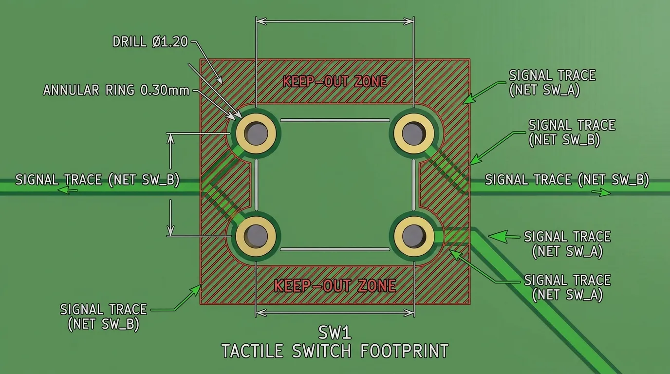
PCB Layout and Footprint Design for DIP Tactile Switches
Getting the PCB footprint right is as important as choosing the right switch. A mismatched footprint creates clearance problems, weak solder joints, or switches that sit at an angle on the board.
The standard pin pitch for DIP tactile switches is 2.54mm — the same pitch used for most standard through-hole components. This means the switches integrate cleanly into PCBs designed with standard grid spacing. Drill hole diameter should be sized to the pin cross-section with a small clearance: typically 0.9–1.1mm for 0.5mm square pins, allowing the pin to pass through without play.
Key PCB layout rules:
- Pad annular ring: Keep a minimum 0.3mm annular ring around each drill hole for solder bonding area
- Keep-out zone: Maintain at least 1mm clearance around the switch body to allow the actuator to depress without interference from adjacent tall components
- Silkscreen alignment: Place the switch reference designator and polarity marker clearly on the silkscreen so assembly technicians can orient the switch correctly
- Trace routing: Route signal traces away from the mechanical support pins — the mechanical pins are not electrically active and should remain unconnected in the schematic
- Stress relief: For high-cycle applications, avoid routing critical signal traces directly under the switch body, as repeated mechanical loading can stress the substrate in that area
For broader context on through-hole mounting techniques and PCB design guidelines, the through-hole tact switch guide covers additional design principles relevant to THT assembly.
Soldering DIP Tactile Switches: Methods and Best Practices
DIP tactile switches support two primary soldering methods: hand soldering and wave soldering. Each has specific requirements to avoid damaging the switch or compromising joint quality.
Hand soldering is the most common method for prototyping and low-volume production. Insert all 4 pins through the PCB, press the switch body flush against the board surface, and hold it in place while you flip the board. Apply solder to each pad at around 250–300°C iron tip temperature. Dwell time should be under 3 seconds per pin to prevent thermal damage to the internal dome or housing. Allow all joints to cool before handling.
Wave soldering is used in automated through-hole assembly lines. DIP tactile switches designed for wave soldering use crimped PC terminals — a termination style where the leads are bent outward at the base, locking the switch against the board surface before solder reaches it. This prevents the switch from floating or misaligning as it passes over the molten solder wave. Always verify that your chosen DIP switch is rated for wave soldering and specifies the correct preheat and wave temperature limits in its datasheet.
Common soldering mistakes to avoid:
- Over-heating the switch body — exceeding 300°C for more than 3 seconds can warp the housing and deform the dome spring
- Applying solder only to 2 of the 4 pins to "save time" — all 4 pins must be soldered for full mechanical stability
- Using flux-heavy solder without post-cleaning — flux residue can migrate inside the switch body in open-type designs and cause contact contamination over time
- Skipping inspection — always visually verify all 4 solder joints are fully formed with a concave fillet before board testing
Common Applications for DIP Tactile Switches
DIP tactile switches appear across a wide range of industries precisely because through-hole construction is robust, reliable, and easy to replace in the field.
| Industry | Example Application | Why DIP Is Preferred |
|---|---|---|
| Industrial control | Machine operator panels, PLC control interfaces | High-cycle durability, mechanical robustness under gloved use |
| Audio / professional equipment | Mixing desks, amplifier control boards | Stable mounting for frequent user interaction |
| Medical devices | Diagnostic handheld instruments | Rework-friendly, inspectable solder joints |
| Automotive prototyping | Dashboard switches, test rigs | Through-hole joints withstand mechanical vibration better than SMD |
| Consumer electronics | Appliance control panels, home automation modules | Cost-effective, widely available, compatible with hand assembly |
| Hobbyist and prototyping | Arduino, Raspberry Pi, breadboard circuits | Directly insertable without soldering, easy to swap |
One practical note: DIP switches are particularly well-suited for any device where the operator uses the button repeatedly throughout the workday. The 4-pin through-hole anchor prevents the gradual pad lifting that can occur with SMD switches in similar high-use scenarios.
How to Choose the Right DIP Tactile Switch
Selecting the right DIP tactile switch is a sequential process. Work through these factors in order, and you will eliminate incompatible options quickly.
| Selection Factor | What to Determine | Why It Matters |
|---|---|---|
| Body size | 6×6mm, 12×12mm, or custom? | Determines PCB footprint and cap compatibility |
| Actuation force | 100gf / 160gf / 250gf | Controls user feel and accidental-press risk |
| Actuator height | Flush / standard / tall | Must match enclosure depth and panel cut-out |
| Lifecycle requirement | Calculate: daily presses × years × 365 | Determines minimum rated cycles needed |
| Contact material | Gold vs silver plating | Gold for low-voltage signal circuits; silver for standard logic |
| Operating temperature | Check device deployment environment | Prevents premature seal failure or dome fatigue |
| IP rating needed | Open / sealed / IP67 | Required for harsh, wet, or dusty environments |
| Pin configuration | 2-pin / 4-pin / 5-pin | 4-pin standard; 5-pin for extra mechanical stability |
| Soldering method | Hand / wave / reflow? | Determines termination style (crimped PC pin for wave) |
| Compliance requirements | RoHS / lead-free required? | Mandatory for products sold in EU, UK, California |
Tip: For most buyers specifying a general-purpose DIP tact switch for an industrial or consumer application, the answer is: 6×6mm body, 160gf actuation force, 4-pin layout, gold-plated contacts, 1M cycle rating, RoHS-compliant. That combination covers the majority of designs without over-engineering or under-engineering the component.
Common Mistakes to Avoid
| Mistake | Why It Happens | How to Avoid |
|---|---|---|
| Wrong footprint dimensions | Copied from a different switch or estimated rather than checked | Always use the manufacturer's datasheet for exact pin spacing and body dimensions |
| Mismatched actuation force | Defaulting to whatever is in stock | Specify force based on application — industrial needs firm; medical needs light |
| Under-rated lifecycle | Not calculating actual expected cycles | Estimate daily use × product lifespan in years × 365 |
| Only soldering 2 of 4 pins | Attempting to speed up hand assembly | All 4 pins must be soldered — mechanical stability depends on it |
| Thermal damage during soldering | Iron dwell time too long | 3 seconds maximum per pin at no more than 300°C |
| No flux cleanup on open switches | Assuming flux is harmless | Clean boards with appropriate flux remover after soldering open-body DIP switches |
| Ignoring IP requirements | Assuming a standard switch works outdoors | If any moisture or dust exposure is possible, specify a sealed variant |
| Using silver contacts in low-voltage circuits | Ordering without checking contact material | Check your circuit voltage; below 5V typically requires gold-plated contacts |
Related Guides
If you are working through a broader switch selection decision, the complete tact switch guide covers all mounting types, product variants, and selection logic across the full tact switch range — a useful reference once you have confirmed the DIP type is right for your application.
If you are still comparing DIP against surface-mount options, the SMD tactile switch guide explains SMD-specific design considerations in depth, and the SMT vs SMD mounting differences guide clarifies the assembly-level distinction between the two approaches.
For a broader look at through-hole component design practices applicable beyond just tactile switches, the through-hole tact switch guide is a practical companion resource.
Frequently Asked Questions
What is a DIP tactile switch?
A DIP tactile switch is a through-hole momentary push-button switch where metal pins are inserted through PCB drill holes and soldered to create both an electrical connection and a mechanical anchor. It provides tactile feedback via an internal spring dome that collapses and snaps back with each press.
What is the difference between a DIP and SMD tactile switch?
DIP switches use through-hole pins for stronger mechanical grip on the PCB; SMD switches sit on the surface and bond only to pads. DIP switches are more durable under repeated mechanical stress and easier to rework; SMD switches are preferred for automated, high-volume PCB assembly due to their smaller footprint.
Why do DIP tactile switches have 4 pins if only 2 are needed electrically?
The extra 2 pins serve as mechanical anchors. They distribute pressing force across 4 solder joints instead of 2, significantly extending the switch's service life and preventing joint cracking under repeated use.
What actuation force should I choose?
100–130gf for light, sensitive applications; 160gf for general-purpose designs; 250gf for industrial or safety-critical controls where accidental actuation must be prevented. When uncertain, 160gf is the reliable default.
Can DIP tactile switches be wave soldered?
Yes — models with crimped PC terminals are specifically designed for wave soldering. The crimped termination locks the switch to the PCB before it reaches the solder wave, preventing float or displacement during automated assembly.
What is the standard pin pitch for DIP tactile switches?
2.54mm is the industry-standard pin pitch for through-hole DIP tactile switches, matching the standard grid used in most through-hole PCB designs.
How many cycles do DIP tactile switches last?
Lifecycle ratings range from 100,000 to 2,000,000 cycles depending on construction quality and contact material. Premium models with gold-plated contacts and reinforced spring domes reach the higher end of this range.
Do I need gold-plated contacts?
Only if your circuit operates at low voltages — typically 5V or below. Gold plating maintains consistent contact resistance at low signal levels where silver plating may cause erratic behavior due to surface oxidation.
Are DIP tactile switches RoHS compliant?
Quality manufacturers produce DIP tactile switches in fully RoHS-compliant, lead-free versions. Always confirm RoHS compliance in the product specification before ordering for EU, UK, or California-market products.
When should I choose a DIP tactile switch over SMD?
Choose DIP when mechanical stability is a priority — high-cycle applications, hand-assembled boards, prototype builds, industrial equipment, or any design where easy rework is important. Choose SMD when automated assembly, minimal footprint, and low-profile mounting are the primary constraints.
Conclusion
DIP tactile switches earn their place in demanding PCB designs for a straightforward reason: through-hole pins anchor the switch to the board in a way that surface pads simply cannot match under repeated mechanical stress. For engineers building industrial controls, audio equipment, medical handhelds, or any device that will be pressed thousands of times over its service life, the DIP format delivers mounting stability and repairability that justifies its larger footprint.
The right DIP tact switch for your project comes down to body size, actuation force, lifecycle rating, contact material, and IP requirements — five decisions that can be made cleanly from a good datasheet and an honest estimate of how the device will actually be used. Get those five right, follow the PCB footprint and soldering guidelines, and a DIP tactile switch will outlast most of the other components around it.
If you are still defining the full switch strategy for your PCB, explore Hanxia's complete tact switch range to compare DIP models alongside SMD and other tact switch types in one place.