





12V Switch Push Button: How to Match It to the Circuit
A 12V switch push button may appear to be one of the simplest components in a vehicle, boat or control panel. Tap a button and something comes on. However, behind the scenes the circuit may vary greatly from application to application.
Some buttons are loaded with a small load. Others only send a control signal to a relay, timer and/or electronic controller. The button can either stay where pressed or come back right back or include an LED that needs additional connections.
It's all about what the circuit has to do, and not about the color or shape of the button.
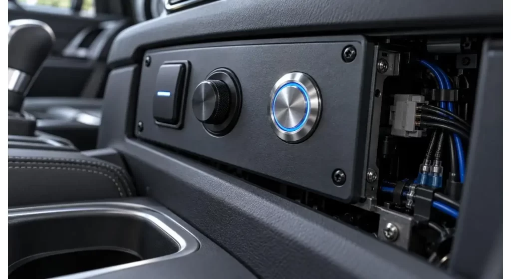
12V Push Button Switch: What is it?
A 12V push button switch is a manually operated switch that is used in a nominal 12V electrical system. When the actuator is pressed it can open or close a circuit.
Applications include: auxiliary lighting, horns, starter control, pumps, fans, door control and vehicle accessories. There are also push buttons which are low current inputs to control modules.
The description “12V” may be used for the connected system, the indicator LED or both. The buyers should still verify the switch contact rating, as voltage compatibility does not determine the amount of current which the switch contacts are able to reliably handle.
The button switch information from Hanxia can be used to get more background information about push operated information in electronic products.
Choose Momentary or Latching Operation
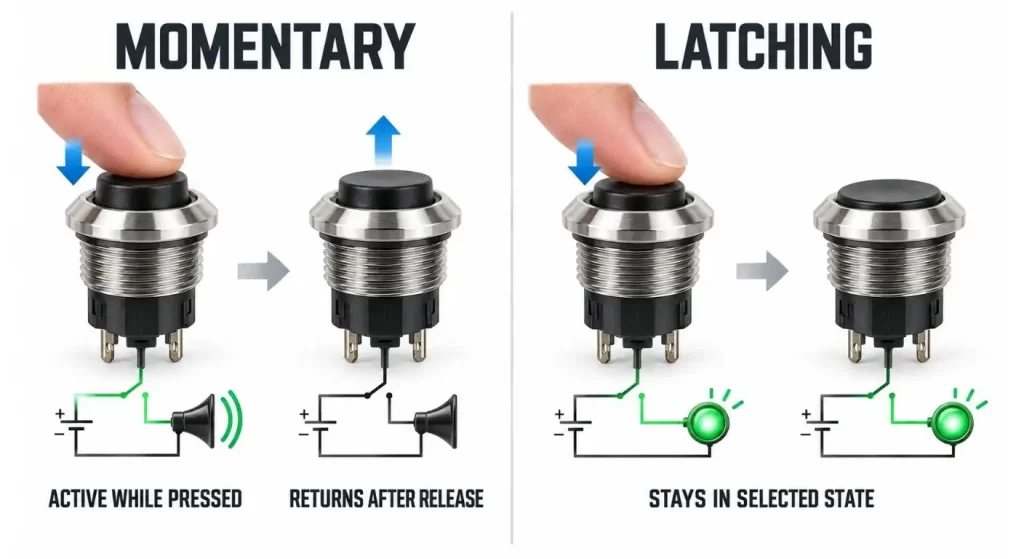
The momentary push button contact is only "on" when it is depressed. When released it returns to its normal position. This action is typically employed with horns, starter signals, reset inputs and temporary control commands.
A latching switch is a switch that changes state upon pressing it and stays in that state till pressing it once again. Can be used for lighting, accessory power and other uses that require a constant power on without having to manually press with a finger.
Both the two actions can appear almost the same on the surface. This operating logic then has to be clearly stated on the drawing and purchase order.
Know what is a Normally Open and Normally Closed Contact.
Normally Open Contact (N.O.) is not connected, but it is connected when you press the button. Commonly used to start or activate a function.
Normally closed contact is a contact that is normally closed and opens when the button is pressed. Can be used in stop circuits, interlock or monitoring circuits. Some switches are capable of both types of contacts and usually have both types of contacts available as separate terminals.
Normal means as it is when it's not being pressed or powered. Verify the circuit using a continuity tester and not by only the position of the terminals.
| Control Requirement | Recommended Action | Typical Contact |
| Horn activation | Momentary | Normally open |
| Engine start command | Momentary | Normally open |
| Reset input | Momentary | Normally open |
| Accessory lighting | Latching | Normally open |
| Stop or interruption command | Momentary | Normally closed |
| Two alternative signals | Momentary or latching | SPDT |
Don't Mix Up Voltage Rating and Load Capacity!
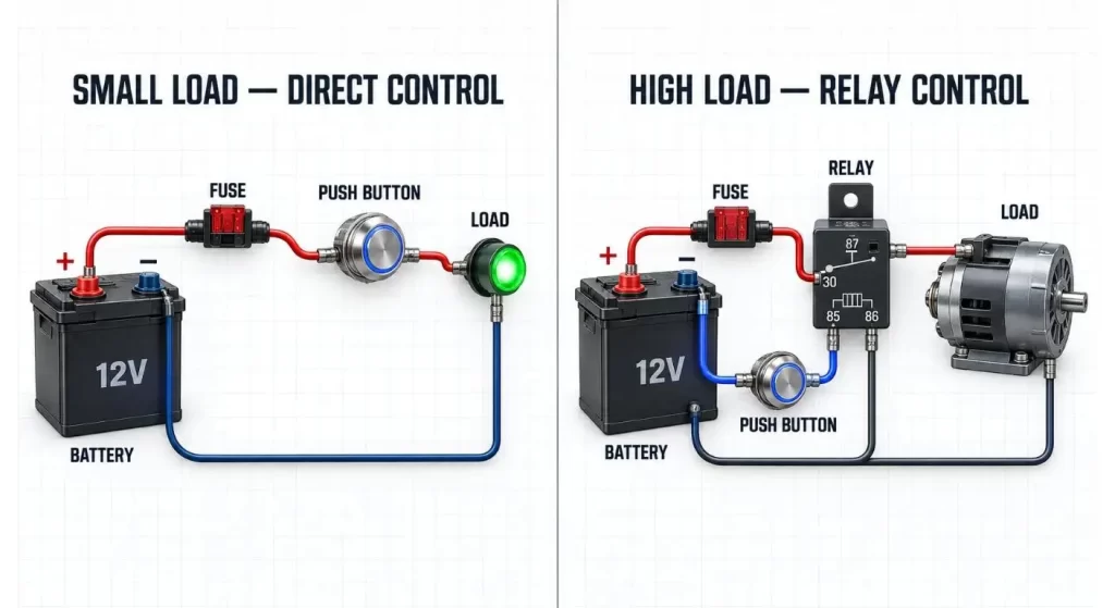
Not all 12V loads can be used with a switch that is rated for 12V. A small LED lamp and a powerful motor can use the same voltage, but have very different currents.
Some lighting systems, motors, pumps and solenoids will have a large startup or inrush current. This is because it can harm contacts even if the running current is seemingly normal.
Check the load type, steady current and peak current. If the load is over the practical switching capacity of the switch engage a suitable sized relay operated by the push button rather than passing the load through the push button.
If the power control is fixed on / off, buyers can also make an application comparison with the rocker switch range that is available.
Construct an LED circuit on a separate piece of paper:
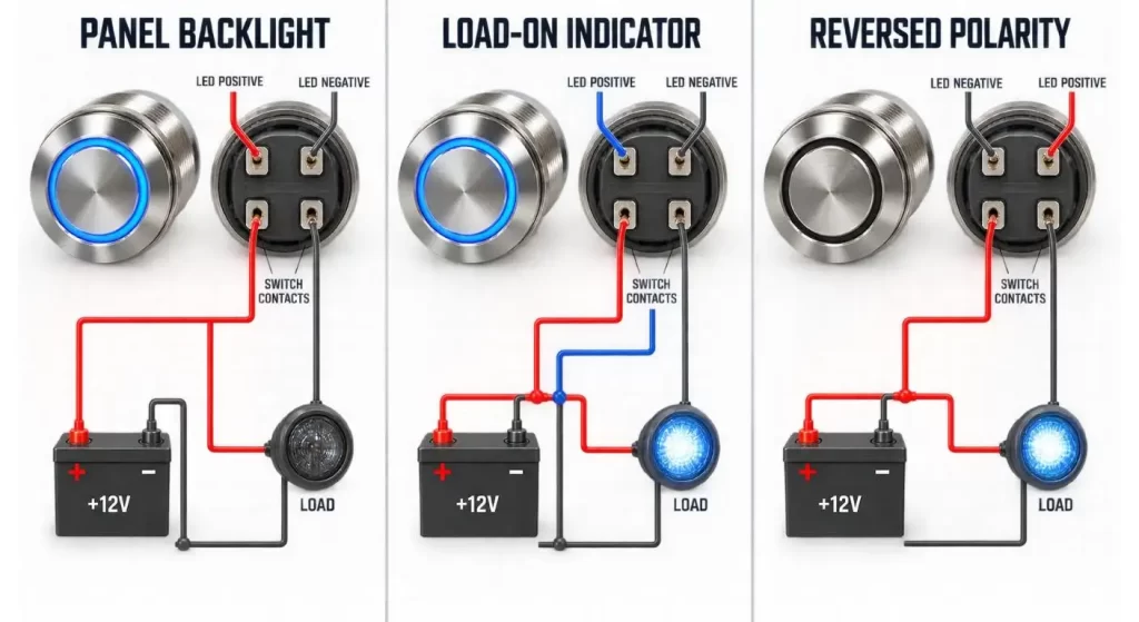
The illuminated push button, 12V, could have contacts on it and other terminals for the LED. Many times these circuits can be wired either of two ways.
The LED can be always on when panel power is present, on when the controlled accessory is running or for backlight for night time identification. There is a wiring plan that is appropriate for each behavior.
LED polarity matters. When the mechanical switch is good, switching the positive and negative can prevent illumination. Also verify that the LED is voltage compatible for the system and not assume that there is an external resistor.
Make Selection of Correct Pole and Throw
One circuit is operated by an SPST push button switch that has a simple open-close operation. An SPDT is a switch that will mate one common terminal to either of two paths, and can also provide alternative outputs.
DPST and DPDT versions control two circuits at the same time. They may be of value in situations where connection of the signal path must be changed in conjunction with the power path, but they do need additional terminal and space.
Don't select a multi-pole switch just because it looks like a more versatile switch. If the circuit needs can be fully satisfied with a simpler configuration, wiring and troubleshooting it will be easier.
Appraise the Mounting Design
Panel cutout diameter, thread length and maximum allowable panel thickness should be verified prior to the machining of the enclosure. The laying up may be too thick so that too little thread remains for the retaining nut.
Also see the back depth. The space requirements for the switch body, terminals, connector and cable bend can be significantly larger than what is shown in the front actuator.
Anti-rotation features can ensure that the switch body does not rotate when the nut is tightened or with frequent use. The sealing washer needs to be flat and cannot be damaged because of an irregular panel surface.
Take Water, Dust and Vibration into account
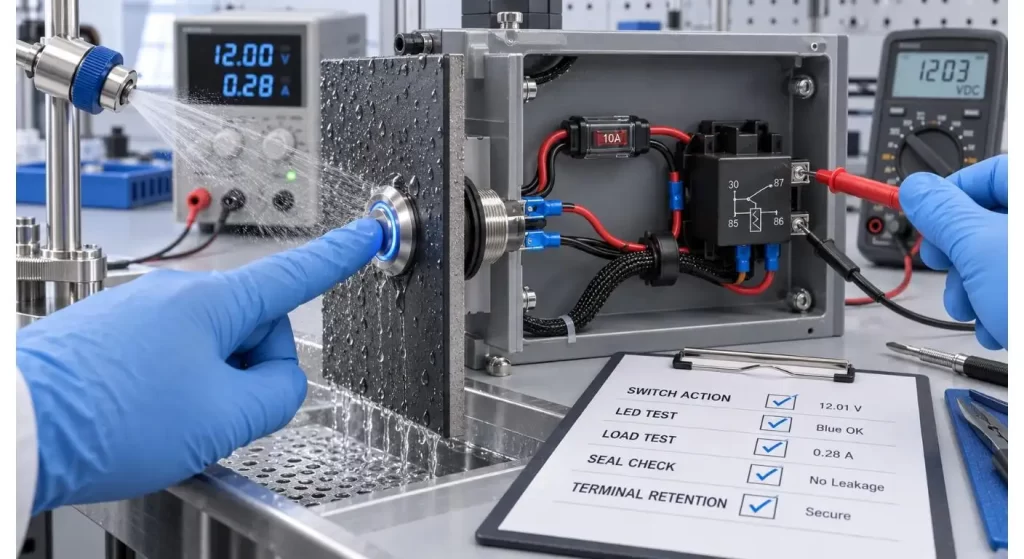
In automotive, marine and outdoor control panel applications, the control panel can be subjected to water spray, dust, vibration and temperature fluctuations. Not just the front of the switch needs to be protected, but the installed assembly.
Moisture may enter via terminals, through cable joints or an improperly installed gasket. Boots, heat shrink tubing or a protected connector may be required on rear terminals.
Vibrations can cause nuts and push-on terminals to become loose. The cable movement should not be directly applied to the switch with wire support and strain relief.
Hanxia's automotive electronic solutions give components deployed in the vehicle control environment related application context.
| Installation Area | Main Exposure | Feature to Verify |
| Interior dashboard | Heat and repeated use | Temperature and mechanical life |
| Motorcycle panel | Rain and vibration | Front seal and terminal retention |
| Boat console | Spray and corrosion | Gasket and protected connectors |
| RV utility panel | Multiple DC loads | Circuit labeling and fusing |
| Industrial enclosure | Dust and cleaning | Sealing and chemical resistance |
| Engine compartment | Heat and cable movement | Rear protection and strain relief |
Build Protection Around the Switch: Add an extra layer of protection for the switch.
The wiring should be protected by a fuse or circuit breaker as per its current carrying capacity and design of the circuit. The protective device should be located in such a way that it would not result in an unprotected conductor for an upstream wiring fault.
Switching inductive loads can cause voltage overshoots which may need to be controlled with suppression components. If not properly protected, arcing can reduce the life of the contacts, or cause interference to other electronics in the area.
Ground wires must be of a proper size and hookup. Both the LED ground and load ground can be a common ground system in the vehicle, but they must have a clear, reliable ground path.
Test Installed Button Prior to Production.
Test the button to see how it performs under the voltage, load and wiring to be used. Test for momentary or latching, contact logic, LED output and relay response.
Insert it many times and observe the drop in temperature and voltage. When used outdoors, consider water exposure post switch installation in the actual panel.
Production-intent terminals and cable size should be included in a functional prototype. For custom markings, colors or wiring, please contact the Hanxia contact team with the specification for evaluation.
Conclusion
The complete control circuit should be designed to use a 12V push button. It must have matching action, contact structure, current capacity, and LED wiring and mounting structure.
If you specify these requirements prior to ordering, you can avoid other troubles like wrong switching logic, non-working indicator, overheated contacts or poor sealing of the panel.
FAQ
Q1. What is the difference between 'Momentary Push Button' and 'Latching Push Button'?
Momentary button - returns to its original position when released. Latching button keeps on or off till it is pushed again.
Q2. Is it possible to have a 12v push button switch to turn a light on or off?
It can when you can choose a switch that has a safe rating that adequately handles the current & inrush of the light. Normally a relay should be used with higher loads.
Q3. Why switch works but the LED is not on?
Contact circuit and LED circuit can have individual terminals. Test LED polarity, LED voltage rating and ground connection.
Q4. What are the meanings of the NO, NC and COM?
NO is normally open, NC is normally closed and COM is the common terminal. This relationship needs to be confirmed in the datasheet or by using a meter.
Q5. Is it possible for a waterproof button to become waterproof after installation?No: Gaskets, panel openings, rear terminals and cable joints have an impact on the installed protection.
