


Mini Slide Switch Manufacturer: Build Around the Slider’s Travel | Hanxia
A mini slide switch provides a convenient physical memory for a small electronic device – the user leaves the actuator where he or she placed it. That can help you identify a power setting or mode with ease, without opening a menu. But reducing the size of the component will also lead to a more difficult to access, move, or interpret control.
When it comes to designing handheld devices, remotes and compact audio products, the first step for designers is to select a mini slide switch manufacturer. The most successful outcome relates to a well defined circuit state and a good sliding motion, which can both be maintained in the enclosure assembly and production. From the start consider the travel path to be part of the product architecture.
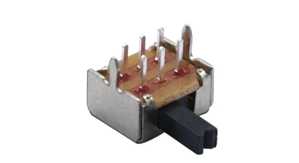
Be sure to begin with the Task Behind the Sliding Motion
Determine the reason to have a physical slider in the product. It can be a continuously applied power setting, it can be used to distinct two modes of operation or it can be used to maintain an active service configuration. Different expectations of movement and blockage of movement are generated by each purpose.
A regularly used control should be easily accessible when handling it. Deliberate access may be required to a service setting, however. Recessing the actuator will help to prevent unwanted changes, however recessing it too far will cause a small slider to be difficult to use.
Hanxia's construction options are a few of those available in their slide switch range. If the selection is to be reduced, state the user, frequency of use and location on enclosure. This brief helps to avoid a small footprint being the only selection criteria.
Select Direction of Access in the Pre Freeze the PCB
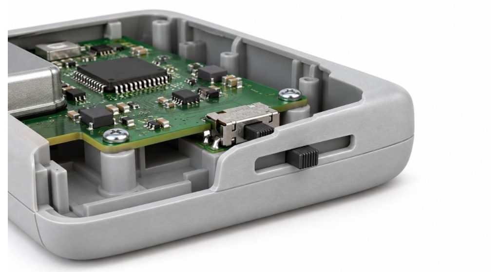
There are differences between the position and geometry of enclosure of top access and side access. The selection of a board edge control might be appropriate for a thin, handheld housing; a top accessible actuator may be better under a panel opening. Take into account the way the device is held while it is in use.
Draw the whole motion of the actuator with respect to the enclosure. Add finger access, adjacent controls and space required to access both end positions. The actual end that is visible must be usable at that end and not just through the midpoint of the vehicle represented in a drawing.
Hanxia's right angle slide switch is one of the constructions to try out for side access. Before using the geometry of the proposed model/dimensional drawing, they should be confirmed. The product name and photographs of products can help identify candidates, however it is unable to precisely describe the relationship between the PCB and housing.
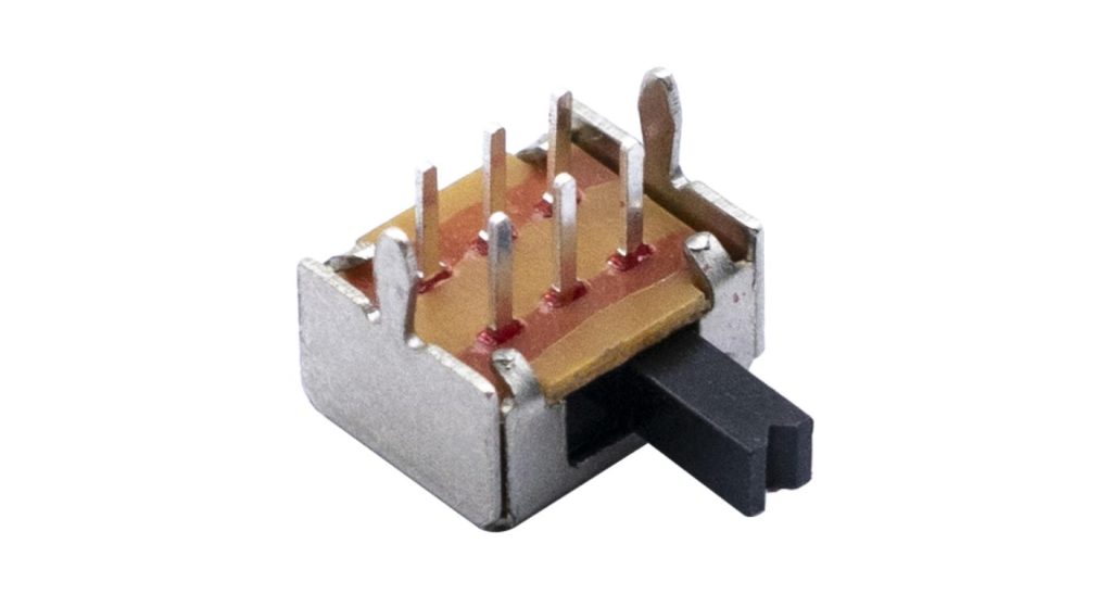
Gap between Slider and Housing Control.
The small slot appears to be clean, but there must be clearance for manufacturing tolerances. The slider's free movement can be effected by the mounting position of the board, the size of the enclosure, the height of the actuator, and the alignment of the assembly. Just nominal CAD clearance isn't an indicator of a strong fit.
Differentiate between integral actuator and external slider cap. Adding an extra cap alters leverage, and may require some guidance from the enclosure. It should not be used to "jam" the switch stem to "correct" a misaligned slot or be used to load the switch in a direction other than that approved for the switch.
Construct a mechanical model that will use the proposed fasteners and supports. Slide the slider in and out by using the full range of movement and note rubbing, tilting and board movement. Repeat after enclosure is closed since the fastening may alter the alignment which may have seemed satisfactory with enclosure removed.
Identify Electrical Conditions and the Transitions between them
Establish the end points at each proposed location. The number of pins is not a criterion for determining the number of positions, poles or independent circuits. Verify these details from a contact diagram that specifies the viewing direction and the terminals' numbers.
Make an assumption about what may happen to the circuit when it moves. There are some mechanisms that will temporarily open the current connection before initiating the next one, or some that overlap the connections. For the selected model request transition behavior where interruption / overlap is important for the application.
If the input to the controller is subject to a transient or fluctuating value, specify the controller's action in such cases. Direct Switching: Check voltage, current and load characteristics versus rating. The Hanxia's SPDT slide switch listing should be taken as a starting point to discuss and choose a circuit; the afterword circuit should be determined by the approved documentation.
So that Each Selected Position is Easy to Recognize.
It should be possible for the user to determine when the slider is set to a position where it is valid. Determine detent definition, the consistency of movements and the amount of force to come out of a position. Even if it overshoots and/or displaces the entire device, it is not necessarily indicative of greater resistance.
Reconsider the relationship of the position of the actuator to the markings on the enclosure from the user's perspective. When the board is installed backwards, the circuit may seem to be running in reverse. Refer to a common agreed to view in checking artwork, mechanical drawings and functional behavior.
When designing for a 3 position setting, then think about the center setting as a first. Can be more difficult to choose and operate than either end stop. Don't depend on an engineer carefully positioning a loose component under good lighting for verification of selection (during realistic handling).

Guard against Performance During Assembly and Normal Exposure
Successful Loose Sample may have different behaviours after soldering or cleaning. Check construction for mounting procedure, allowable operating temperatures and cleaning guidelines. Don't assume that if a metal shell is closed then the mechanism is washable.
Discuss handling and packaging with assembler. Unappropriate fixtures or other assemblies in the vicinity of small exposed actuators can cause damage to the actuators. If automated placement, check pickup access and package orientation and any other pertinent handling instructions prior to pilot run.
The fact that there is every-day exposure also needs to be addressed. Debris, dust and cleaning residue may be trapped around an access slot. Determine the environment and evaluate the proposed switch and enclosure as a whole. Only add protection where necessary, but maintain unrestricted movement of actuators and realistic access to services.
Pick up a Pilot Build, Check Consistency.
The idea is to test the selected design in a pilot construction to see if the design is going to be reproducible during actual constructions. Test various units for access, position recognition, electrical operation and retention of selected position. Explore variation rather than sign off on the most comfortable instance.
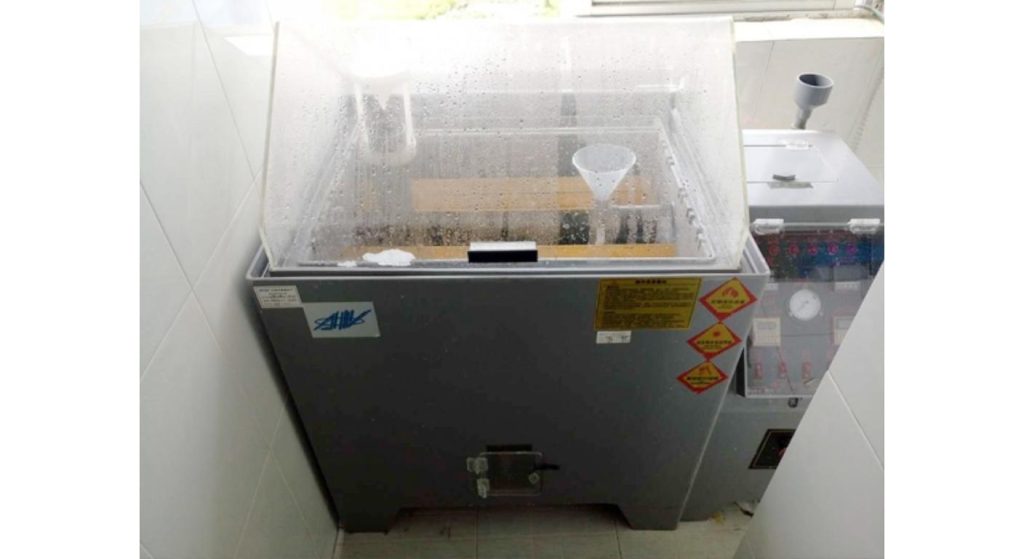
Try out the real product at each location and for typical motion. A power selector must be tested using the electrical conditions it is intended to be used with and a mode input must be tested using the completed controller logic. Don't mix mechanical and electrical acceptance criteria.
| Evaluation Stage | Identification to Record | Comparison Evidence |
| Incoming component | Supplier part number and lot | Loose-part reference |
| After soldering | PCB revision and assembly run | Pre-enclosure test record |
| After enclosure closure | Housing revision and unit ID | Installed operation record |
| After repeated operation | Test unit and cycle conditions | Before-and-after comparison |
| Final approval | Approved configuration revision | Retained reference assembly |
Provide Hanxia with the Information to Change the Recommendation
Please specify the positions, the contact method, the circuit conditions and the mounting method and the space when contacting Hanxia. Provide an enclosure section with the slot and access direction as well as expected operating frequency, environment and demand.
Have team determine a proposed part and verify pertinent drawing, process and sample configuration. Clarify any ambiguity in published information prior to approving. There is a mini slide switch manufacturer who adds value to the market by providing a repeatable part that works with a viable product interface.
Conclusion
The first principle of a reliable mini slide switch design is to have a good movement and the last is to have a well-defined electrical state. Establish access path, enclosure clearance and circuit behavior in parallel with each other. Test and confirm this connection in the pilot assemblies before finalizing the connection for the production of the same structure.
FAQs
Q1. Can use a mini slide switch to make continuous adjustment?
Typically selects specific locations. If continuously variable, evaluate an appropriate potentiometer or other control.
Q2. Is a 3 pin switch always in 3 position?
No., the terminals are different types of counts; the first is a number of terminals, and the second is a position count. Implement both using the “contact diagram” of the model.
Q3. Are there any switches that can get an external slider cap?
Don't take it for granted that it's compatible. Review attachment geometry, leverages, guidance and allowable loads for the actuator.
Q4. Why is there a slider stuck after assembly of enclosure?
This can be a result of slot interference, misalignment or external cap pressure. Make comparisons before and after the house is fastened.
Q5. What information should be given in a sample request?
Describe the state specifications, electrical conditions and mounting. It would be useful to specify the direction of the intended access by adding an enclosure section to the request.
