


Miniature Rocker Switch Manufacturer: Plan a Compact Panel Control | Hanxia
The smallest discernable size is not always the deciding factor as to if a miniature rocker switch functions well, since it will save space on the panel. On the back of the panel, terminals require clearance, wires must be able to be routed and retaining clips must be able to grip the actual enclosure material. The load's requirements are not just the normal running current, but may be greater electrically.
If you're an appliance designer, equipment engineer, or OEM buyer, finding the right miniature rocker switch manufacturer involves finding the right balance of the above relationships. The aim is to design a small-sized control which communicates well with the user and fits into the final product housing while operating as required under the specified switching conditions. Start with the operating sequence of the product, NOT a desired switch photo.
Ensure that the Rocker Position has a clear meaning.
Explain the effect that occurs at each end when it is pressed. A "maintained" rocker will remain in the position they select, and a "momentary" one will come back when it is released. If a center position is required, it is required to be an electrical center position.
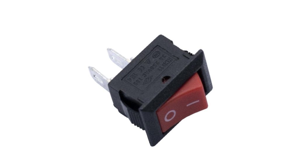
Consider the user's method of access to the equipment. Rear mounted power control could be touch controlled, front panel control might require an obvious state. The orientation, the shape of the actuator and the surrounding space should facilitate that interaction without the need for awkward grasping.
Hanxia's rocker switch series have various operating styles and constructions. On the Drawing of the selected model, determine a suitable family using the range, and confirm the contact arrangement and maintained/momentary action of the selected model. Only the footprints of the paddle can be determined from its appearance.
Create a definition for Load Before Choosing the Smallest Body.
Determine if rocker switches its equipment supply directly, or it switches an input to another control circuit. These are separate assignments. A small switch which is adequate for a control signal is not necessarily good enough for direct power switching.
Note the kind of supply, its voltage, current in operation and start up characteristics. Motors, lamps, capacitive power supplies may offer switching situations which are very different from steady state. Inquire the manufacturer to consider the actual load, and not choose the biggest current value in a list in the manufacturer's website.
Verify the rating (AC/DC) separately. Don't assume one from the other or that a lower voltage voltage means every load is OK. If equipment approval involves component documentation, ensure that this documentation is for the precise model and conditions to be used prior to finalising the electrical design.
Create Cutout around Actual Panel
A snap fit rocker has to fit into the opening as well as into the panel it fits to. Insertion and retention is affected by cutout dimensions, corner geometry, panel thickness and stiffness of material. Fitting in a thin sample plate may not be a good indicator of how the material will perform in a molded enclosure.
Compare supplier's mounting drawing to the production process. The finished opening may be varied or changed by paint, coating, burrs or molding variation. Review components for dimensional tolerances and not just an actual prototype.
Hanxia offers a mini rocker switch listing that's a pertinent compact switch to explore. Get the latest cut out and panel thickness requirements prior to committing enclosure tooling. Once installed, check bezel seating and clip engagement and repeatedly operate paddle to confirm that there is no distortion of the surrounding panel and that the body is stable.
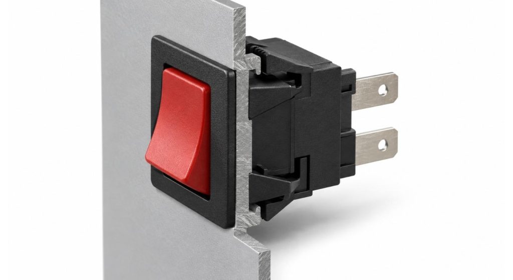
Space in the rear of the panel is reserved.
But the body area for the switch isn't the only requirement for the interior. Add terminal projection, mating connectors, insulation and wire routing. Check the accessibility to assemble and serve, particularly when the switch is located next to a PCB, rib or enclosure fastener.
Select an appropriate termination method based on the approved switch construction. In the case of push on connectors, verify dimensions of terminals and connectors. In soldered connections, adhere to the procedure listed here and refrain from passing any unneeded heat and/or mechanical stress to the housing.
Install support wiring to prevent repeated movement of cables putting the terminals under load or pulling the switch against its retaining clips. Look for wires that may have been moved out of place by the installation of the enclosure; check with the enclosure closed. Maintain necessary insulation distances during that move.
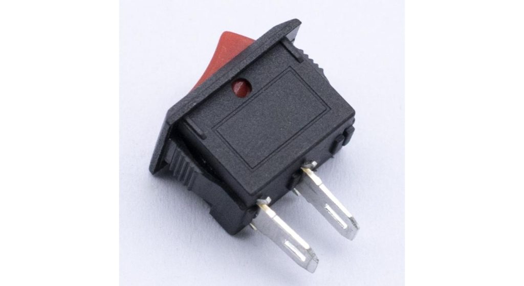
Determine What Light really means
An illuminated rocker can help to identify which position it is in, which position it has been selected to, or that a specific circuit is energized. Those meanings do not equal. Determine the purpose of the message and select the pattern of lamps and the terminal diagram.
Check the voltage levels and electrical connections of the indicator for the desired variant. The number of terminals does not determine how the switch is wired, nor does it indicate which are used for the indicator. Look at the approved diagram, don't make assumptions about wiring from another illuminated rocker.
In the installed orientation review the markings / light output. The indicator must be simple under normal ambient light conditions, but must not mislead the user of the equipment when interpreting the indicator. When it is not possible to illuminate, ask yourself if the physical location and surrounding identification makes the control's function clear.
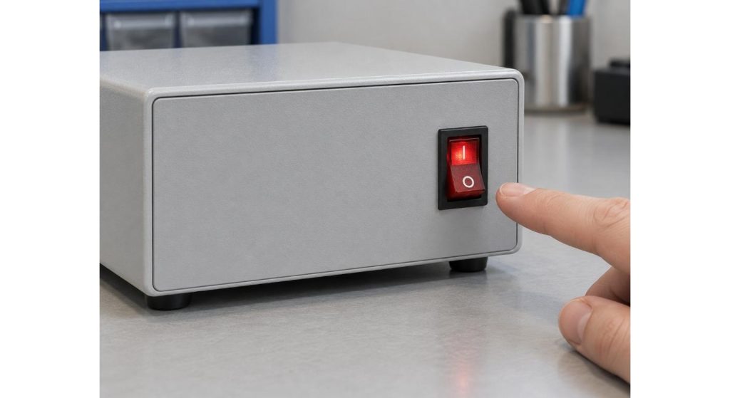
Assess the heat and exposure within equipment.
The switch is exposed to its ambient atmosphere that may be different than room conditions. Installation can be influenced by nearby heaters, power components, restricted ventilation and resistance of the connectors. Check the conditions for the whole selected configuration.
If there is likely to be dust or splashes, establish the exposed edge. A front gasket can be used to protect the front opening without closing the rear gasket. The rating for ingress is not determined by the appearance of a coloured or covered actuator.
Test the set up equipment under representative operating condition. Write the mounting, the electric load, the locations of sources of heat and any temperature data. It is better than a picture of a switch on a bare bench, especially if the final enclosure is a heat-trapping one, or if the wiring routing changes.
Carry out Test of the Control - Real Operating Day
Construct sample into actual enclosure and employ the actual load. This should encompass startup, shutdown and repeated operation, as well as normal handling. Ensure that the state chosen is stable and that there are no movement of the equipment out of position during use of the rocker from the users.
Have appraisal of installation quality with respect to switching behavior. Look for movement of the panel, loose connectors, broken and burned insulation, and panel feel changes. Specify the endurance conditions with the supplier – a mechanical cycle does not give electrical life under all loads.
Ensure that the sample identification and test conditions remain with the test results. If a problem occurs, note the time of occurrence and if it occurs after assembly, after warming, after vibration or after switching on and off. The observations provide the manufacturer with a valuable initial foothold for a full investigation of the installation.
| Operating Stage | Evidence to Record | Acceptance Reference |
| Initial installation | Bezel seating and retaining clip engagement | Approved mounting drawing |
| Cold startup | Switching behavior and load startup record | Agreed load conditions |
| Warm operation | Relevant temperatures and control behavior | Component and equipment limits |
| Routine shutdown | Contact opening and indicator response | Approved circuit diagram |
| Service access | Connector removal and panel condition | Approved service procedure |
Send Hanxia a Panel and Load Brief.
If you contact Hanxia, please mention what you intend to do, the circuit, the power supply, the characteristics of the load, the drawing of the panel, and the rear clearance available. Cater for termination preferences, environmental exposure, marking, expected quantities and required supporting documents.
A helpful mini rocker switch producer ought to link its proposal with those requirements. Review and agree upon the following with configuration, installation drawing and associated test evidence. This provides engineering and purchasing a common basis for repeat orders, and maintains a small panel control in step with the product that it serves.
FAQs
Q1. Does a small rocker fit all small equipment?
No, don't count rear terminals, connectors, wiring space or panel retention. This is just the part of the paddle that is visible, the rest is installed under the water.
Q2. What happens if an AC value is applied as a DC value for a switch?
Don't take equivalences for granted. Have a rating for actual DC voltage, current and load.
Q3. Is it always a good indicator that equipment is running if an illuminated rocker is shown?
No. It's meaning is based on the indicator circuit. Draw the indication and check the wiring diagram.
Q4. A snap fit rocker moves after it is installed, why?
This may be due to cutout variations or panel thickness or due to improper clip engagement. Examine completed opening and mounting system.
Q5. What to include with a request for a sample?
Include load data, action to be taken, drawing of the panel and termination requirements. Make sure to include exposure conditions and evidence for approval.
