





Slide Potentiometer with Switch: One Control, Two Functions
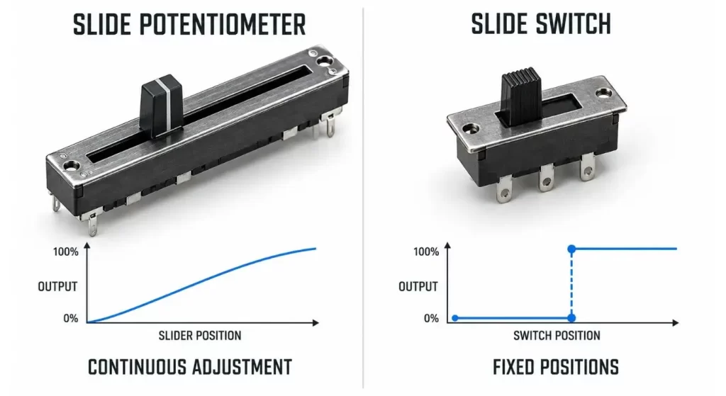
A slide potentiometer with switch is a combination of two related functions that are electrically different. The difference between the potentiometer and the switch is that the potentiometer is continuous over its travel while the switch is a defined on-off (or signal change) event.
This configuration can be used for a product requiring more than just a simple level control. For instance, a channel on a mixer can be turned up and down over a wide range of the fader and at the bottom of the fader's range can be muted. The same concept can be applied to analog interfaces for industrial use to provide a positive end position command in addition to analog adjustment.
The problem is, the resistance, the switch logic, travel, feel and circuit configuration have to work together. It is not usually sufficient to choose the component based on its external characteristics.
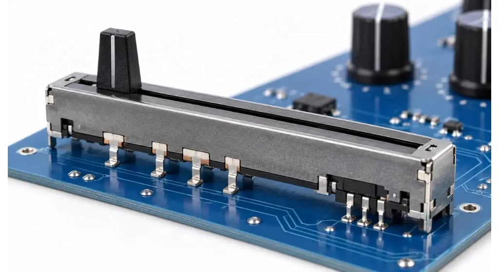
Slide Potentiometer with Switch – What is it?
Slide potentiometer is one type of the variable resistor controlled by moving a slider on a straight path. It typically consists of two ends of a resistive element and a movable wiper that gives a variable output.
An integrated switch is a switch that is operated by separate terminals. It can engage at the start or end of the trip, on a specific detent or by another press action. The switch will not replace the output of the potentiometer, but it will provide an additional state for the circuit to sense.
This is unlike a slide switch that is used to switch between two electrical connections.
Why to combine Adjustment and Switching?
Combining both functions can minimize the number of controls that show up, and also improve the user sequence of the app. A fader moving away from 0 will cause a channel to wake up and a fader moving back to 0 will cause a channel to go to mute or power-off.
On professional audio products, the switch could be used as a channel status switch, or for selecting a cue or muting a channel. Lighting controllers can be programmed to do an end position blackout command and dim the lights. In an industrial panel, it could be used to indicate that a manual operation has reached a minimum or maximum limit.
This architecture also allows space savings in the panel. It should be selected, however, because the combined action helps to fulfill the user's tasks, rather than just because one part seems to be less expensive than two controls.
What is the Potentiometer Function?
Start with the specified value of resistance and tolerance. This value will vary with the surrounding circuit, input impedance and type of input signal.
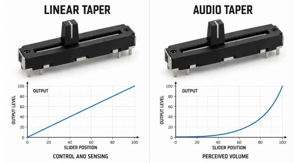
Now select the taper. A linear taper is where the resistance varies in a fairly regular fashion over the slider's travel and is used in control, sensing and lighting applications. Audio Taper or Logarithmic Taper better adjusts the level in a natural manner.
Do not state it as “smooth,” just because it is smooth. Indicate resistance, taper, acceptable tracking behavior and effective electrical travel. Two resistive elements need to be closely matched as well in dual channel audio controls.
| Parameter | Available Decision | Design Impact |
| Resistance | Selected for the circuit | Loading and output range |
| Taper | Linear or audio | Relationship between travel and output |
| Number of gangs | Single or dual | Number of controlled channels |
| Tolerance | Standard or tighter | Unit-to-unit accuracy |
| Tracking | General or matched | Balance between dual channels |
| Electrical travel | Defined active range | Usable adjustment distance |
Determine When the switch Should Operate
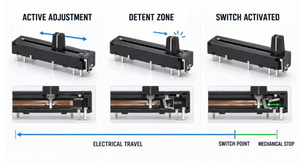
The switch can be made to switch at the lowest position of the slider, at the top position of the slider or close to a mechanical detent. It should have an operating point that is determined with respect to the electrical travel.
However, if a mute switch is triggered too early, the signal may disappear before the slider gets to its "visible minimum". If it does not run until the proper time, the user might hit the mechanical stop without giving the desired command.
There needs also to be a switch logic. Normally open and normally closed contacts have different functions. Verify that changes are made on entering the end zone, on leaving the end zone and/or on pushing the slider separately.
When only discrete position selection is needed, then a dedicated slide switch might be more suitable. Some examples of fixed-position configurations are provided in Hanxia's slide switch range.
Align the Match Mechanical travel to the Interface.
The overall travel is not equal to the effective travel of electricity. Mechanical distance is the distance travelled by the slider and it can be greater than the distance through which the output is changed.
The longer the travel, the more physical control given to the user, such as mixing consoles and test equipment. Short travel is efficient in terms of space saving, but is more sensitive to hand movements when making small adjustments.
The control panel door should be able to move around completely without rubbing. See lever height, knob size, mounting hole position and gap under the panel. The slider will need to reach its desired switch point before the knob first hits the enclosure.
Take into account the Feel, Detents and Operating Force.
The movement of the slider should be smooth and not loose or stiff. Its feel is affected by its lubrication, guide construction, contact pressure and dust protection.
A detent can make it easier for the user to know where the switch is by just feeling it, rather than looking at the switch panel. However an excessive detent is likely to make fine adjustment near the end of travel difficult.
Operating force specification: Normal sliding operating force should be separated from the force to go over the detent or to actuate the switch. This is important when you have several faders that need to sound the same when played on the same controller.
Signal noise and channel tracking control.
A noisy or erratic reading is created when the wiper comes in contact with the resistive element if it is contaminated, worn or electrically mismatched. Important consideration in grounding and routing sensitive audio and measurement circuits.
Where possible avoid routing analog traces near power switching routes. Where the integrated switch is used to control a relay, motor or other inductive load, make sure that adequate circuit protection is used and the switching transient does not couple into the potentiometer signal.
Dual-gang types require channel-tracking measurement, too. Two outputs can agree in the middle of the travel, but disagree at the ends where the errors may be more discernable.
Take great care in planning the PCB and terminal layout.
It is important that the potentiometer terminals and switch contacts do not get confused in the schematics and PCB layout. It is easy to mix up similar looking pins while wiring the prototype.
Confirm the pin numbering, mounting orientation and direction of increasing output. Mechanically reversed installation can cause the on-screen or printed scale to reverse the electrical response.
The strength of the PCB is also important. A repeated side force is applied to a long slider by the user, and mounting tabs or other supports might be required. If a separate harness is used for the assembly connection, the possibility of using compatible connectors and connector sockets may be taken into account during the system layout.
| Inspection Item | Verification Method | Main Failure Risk |
| Slider travel | Move between both mechanical stops | Enclosure interference |
| Switch point | Monitor contacts during travel | Early or missed activation |
| Detent feel | Repeat slow manual operation | Excessive force or weak feedback |
| Pin direction | Measure output while moving slider | Reversed control response |
| PCB support | Apply normal side force | Board flex or solder stress |
| Terminal separation | Review schematic and PCB | Signal and switch wiring confusion |
Test the Complete Operating Sequence to verify the system is working correctly.
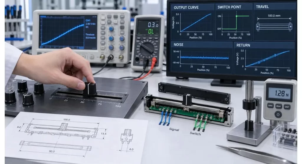
Put the sample into the actual panel and take the output reading throughout the entire travel. Examine minimum, midpoint, maximum and switch changeover point.
Slide the slider in a slow and fast manner. Check for noises, output interruptions and channel imbalance. Repeat the test after cycling, vibration, dust exposure and/or temperature conditioning, if these tests represent the last application.
Most critically determine the sequence in use. The mechanical stop, electrical end point, detent and switch event should be a single, intended action and not four independent tolerances.
What to include in a Purchasing Specification.
A complete request shall consist of a statement of resistance, tolerance, taper, number of gangs, mechanical travel, electrical travel, switch position, contact logic. Mounting style, levers size, knob requirements and planned life span.
Give application, circuit conditions, PCB drawing and quantity to be aimed at annually. If there is no standard component which meets the required architecture, please convey the full requirement to Hanxia technical team for the evaluation of the related switching component.
Conclusion
The slide potentiometer with switch works best when the continuous adjustment and the discrete circuit command are used in the same user action. Isn't so much about saving one panel opening as functional integration.
The selection must be coordinated between the resistance curve, effective travel, switch point, mechanical stop and PCB layout in order to achieve reliable selection. Integrate and test all these elements in the final interface prior to the approval of production.
FAQ
Q1. Is Slide Potentiometer Equal to Slide Switch?
No. Potentiometer is a continuously variable resistance and slide switch is a fixed circuit resistance.
Q2. What is the integrated switch for?
It is capable of controlling mute, power, standby or any other logic function. The switch has its own contacts, and does not interrupt the potentiometer signal automatically.
Q3. Linear vs audio taper?
Linear taper changes are a gradual progression with slider position. Audio taper is a non-linear curve, which will give more natural volume change in the perception.
Q4. Does switch activate when fader is at the end of its travel?
Yes, if the component has an end-position switch. The mechanical and electrical activation points should be determined.
Q5. Why is there a noise in slide potentiometer?
The output may be unstable due to dust, wear, contamination, use of improper circuit impedance or poor routing of the PCBs. Testing should be done both for component and circuit.
