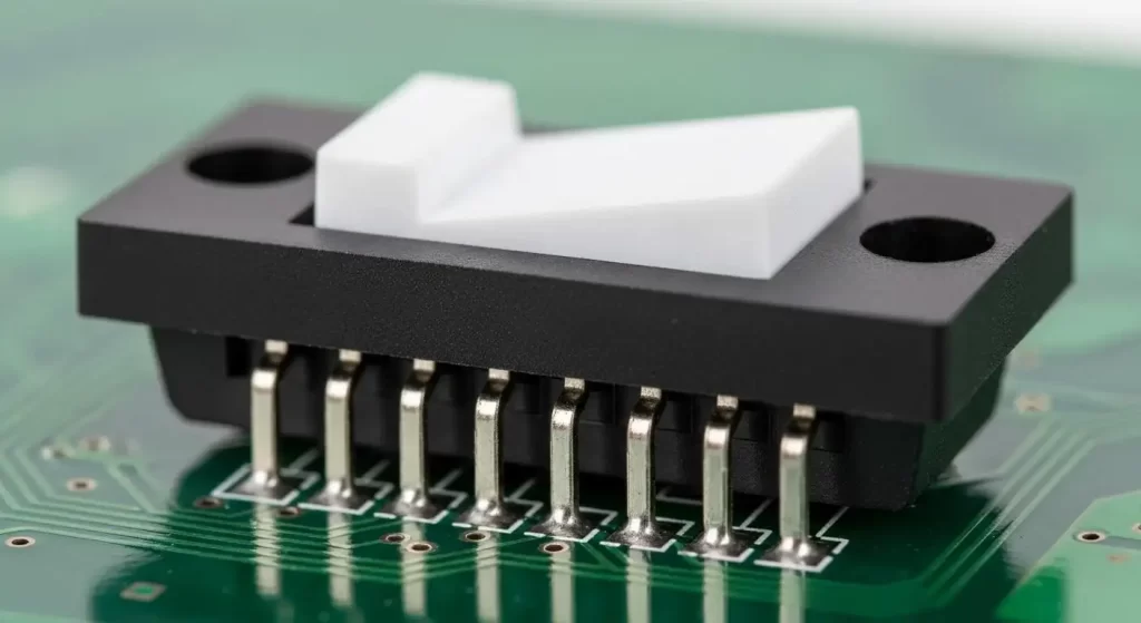
12-Pin Slide Switch : How to Select, Wire, and Test Safely(2026)
A 12-Pin Slide Switch packs surprising flexibility into a compact form, giving you multiple routes for modes, signals, and low-voltage rails without rewriting firmware. In 2026's high-density layouts and quick releases, the right slide switch eases routing, stabilizes performance, and speeds verification. The keys are straightforward: pick the right topology, wire it with intention, and test it like your product depends on it - because it does.
Choosing the Right Configuration for Your Application
Start with function, not part numbers. “12 pins” describes terminal count, not necessarily the internal configuration. Map your circuit first, then match it to a pole/throw arrangement.
• Match topology to the job: Decide whether you need independent SPDT channels, paired DPDT blocks, or a multi-pole, multi-throw matrix. Common 12-pin mappings include 6P2T (six SPDT circuits) and 4P3T (four poles with three positions each) for coordinated mode switching.
• Consider the load: Resistive loads are straightforward. Inductive loads such as relays, solenoids, and small motors demand flyback suppression and current derating to preserve contacts.
• Respect electrical limits: Typical slide switch ratings hover around 0.3–1.0 A at 12–24 VDC for utility power, and 50–200 mA at up to 50 VDC for signal-level duties. Select with margin; a 30–50% headroom is a good starting point for switching under load.
• Protect low-level signals: If you're routing millivolt or microamp signals, favor gold-plated contacts, initial contact resistance at or below 50 mΩ, and devices explicitly rated for low-level switching (e.g., 25 mV/1 μA).
• Check the feel and format: Actuation force in the 1–3 N range with 1.5–2.5 mm of travel produces a positive, repeatable action. Confirm the actuator height, footprint, and keep-out so it clears neighboring components or panel hardware.
• A word on safety: Most 12-Pin Slide Switch models are intended for SELV/PELV domains, not 120/230 VAC mains. If you need mains isolation or regulatory compliance in appliances, select switches specifically certified for that role and maintain creepage and clearance per your standard.
Decoding Pinouts and Planning the Wiring
Before solder touches pad, decode how the internal sliders traverse the terminals. Manufacturers do not standardize numbering or grouping, so always read the datasheet and verify with a meter.
• Identify commons and throws: In each pole, a “common” wiper moves between two or more “throw” terminals depending on the slider position. Use continuity mode to map every position.
• Label positions physically: Mark “Pos 1 / Pos 2 / Pos 3” on your prototype or panel to guard against assembly mistakes and to speed production training.
• Keep sensitive traces short: For high-impedance or RF-sensitive lines, minimize loop area and route away from noisy digital edges and switching regulators.
• Separate analog and digital: Assign poles so that analog lines never share an adjacent route with fast digital transitions if you can avoid it. Add ground stitching vias between zones on multilayer boards.
• Strain-relieve harnesses: If you panel-mount and wire by hand, add heatshrink and tie-downs. Avoid bending wires at the solder joint; that's where fatigue starts.
Common 12-Pin Layouts You'll Encounter
• 4P3T (Four Poles, Three Throws): Twelve terminals arranged as four identical switching sections. Ideal for selecting operating modes across synchronized signals - think “A/B/C” paths for four lines that must move together.
• 6P2T (Six SPDT Channels): Twelve terminals form six on–on circuits tied to one slider. Use when you need a DIP-switch-like bank operated with a single action.
• 2P6T (Two Poles, Six Throws): Less common in slide form but possible. Useful for rotary-style selection implemented in a linear slider format.
Wiring Patterns That Reduce Noise and Errors
• Mode buses: Route the common of each pole to your source bus and the throws to destination nets (Mode A/B/C). Label nets clearly to match position silkscreen.
• Low-voltage rails: If switching 5–24 V rails, switch the positive line; keep grounds common to reduce ground offset surprises.
• Mixed signals: Assign one pole per signal type. For example, pole 1 handles analog reference, pole 2 handles digital enable, poles 3–4 route differential control signals, and poles 5–6 switch LED indicators for the user.
• Inductive loads: Always add suppression. A diode across a relay coil, or an RC snubber for AC-like or bidirectional situations, tames voltage spikes that weld contacts.
Safety and Test Protocols You Shouldn't Skip
Every new lot - and certainly every new design - deserves a short, deterministic test plan. A few minutes on the bench prevents intermittent field failures and reduces debug time.
• Continuity mapping: Verify that each pole only connects to the intended throw in each slider position. Record a quick map as a reference drawing for production.
• Contact resistance: Measure milliohm-level resistance with a four-wire meter if available. New parts typically come in at or below 50 mΩ; establish a limit (e.g., 100 mΩ) for post-cycle inspection.
• Insulation resistance: Between isolated circuits, aim for 100 MΩ or higher at 100 VDC for signal work. For harsher environments, test at 500 VDC per your reliability target.
• Dielectric withstand: Quality 12-Pin Slide Switch products often survive 500 VAC for 60 seconds between terminals or terminal-to-frame; confirm the exact test in the datasheet.
• Life and feel: Exercise 5,000–10,000 cycles to simulate realistic use. Monitor for rising contact resistance and any change in actuation force or tactility. Electrical life at rated load is commonly 10k cycles; mechanical life may reach 50k–100k cycles.
Debounce, Arc Suppression, and Derating
Mechanical contacts bounce - it's physics, not a defect. Expect a few milliseconds of chatter.
• Debounce digital edges: In firmware, start with 5–15 ms of debounce per transition. In hardware, an RC like 10 kΩ with 100 nF cleans edges for simple logic gates; adjust to taste.
• Prefer break-before-make: Most slide switches are BBM by design, which prevents momentary shorts across throws. Call out make-before-break (MBB) if required; confirm vendor timing data.
• Use: Prefer switching with the load off; if not, apply 30–50% derating and arc suppression components.
• Build: Add covers/insulators to hide exposed solder on customer-accessible panels. Use covers or bezels to keep debris out of the actuator slot.
Specs That Matter in 2026 Designs
When comparing datasheets, focus on the few numbers that drive reliability in real products.
• Rated Load: Around 0.5 A at 24 VDC for resistive loads; 50–200 mA at up to 50 VDC for signal-level switching. Interpret specifications as upper bounds, not design objectives.
• Contact resistance: initial not exceeding 50 mΩ (typical). Establish explicit end-of-life or preventive-maintenance thresholds in the test plan.
• Insulation Resistance: ≥100 MΩ at 100 VDC; raise to 500 VDC for high-reliability builds or contamination-prone environments.
• Dielectric Strength: 500 VAC for 1 minute is common; verify whether the spec is terminal-to-terminal or terminal-to-frame.
• Operating Temperature: −20°C to +85°C is typical; for outdoor or industrial hardware, look for −40°C to +85°C and materials that tolerate thermal cycling.
• Actuation Force And Travel: About 1–3 N with roughly 2 mm travel ensures a distinct click without excessive panel flex.
• Materials And Plating: Copper alloy with nickel underplate and gold for low-level signals; tin is acceptable for higher currents. Compliance: Verify RoHS/REACH; UL94 V-0 housing if your safety spec calls for it.
• Environment: Standard slide switches are unsealed - mitigate with sealed/semi-sealed variants or a gasketed bezel/slot in the enclosure.
Board and Layout Considerations That Influence Results
Even a perfect switch can misbehave on a poor layout. Maintain creepage and clearance per IEC 60664 for your working voltage, create keep-outs around the actuator to avoid wicking flux and debris into the mechanism, and route differential pairs symmetrically if you must pass them through a pole. EMI: ground guards; no routing under switch - flux residue attracts moisture.
CTA: Contact HANXIA for 12-pin checklist, wiring maps, scripts, specs, vendors, samples. We'll lock P/T and validate PCB ratings for 2026.