





Vertical Slide Switch: Design the Motion Before Choosing the Part
Many times, a vertical slide switch is the simplest component on a PCB. After that the first enclosure sample comes in.
The actuator is too low, the plastic slider is rubbing against the panel slot or the user must push sideways while the switch body is pushing. All of these issues start with electrical performance issues. They start since the word “vertical” was never clearly defined.
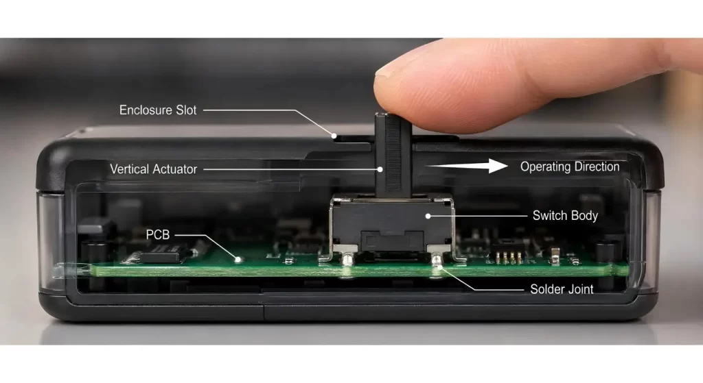
Choose the type of switch motion, how the switch is mounted and how the user is going to access it in advance of choosing a part.
Assess the Product and Determine What it Means to be “Vertical”
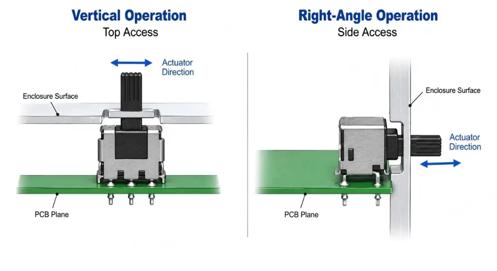
Vertical could refer to an actuator which moves perpendicular to the PCB, a switch body installed on its end, or a control which is accessed from the top of the enclosure. This is not the same set up.
On one drawing, label the plane, direction of operation and surface of enclosure. This will indicate in a flash if you need a vertical actuator, side operated or a right angle slide switch.
The full slide switch range is extremely convenient for comparing actuator forms, positions and circuit configurations prior to determining the footprint.
Start With the Users Finger, it is very small, it sits on the thumb
There needs to be easy access to the switch without it being loose or awkward.
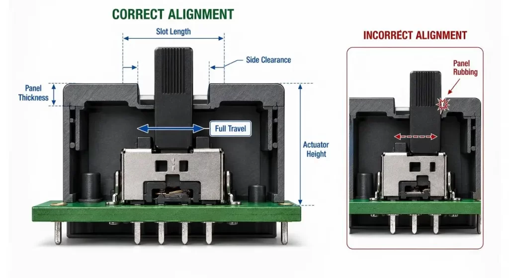
Double check the actuator's height off the PCB, the thickness of the panel, the length of the slot, the direction of travel in the slot, and the clearance around other nearby keys. The short actuator can be hidden behind the housing. Too high of an actuator provides the user with more leverage and can cause unnecessary forces to be applied to solder joints.
The enclosure should facilitate the finger, but not be a second bearing surface. The slider should not be constantly rubbing against the panel as wear and inconsistent operating force may be evident with a working switch.
Match Travel x Required Decision
There are products that require just an ON/OFF option. Some require two signal paths, mode selection or multiple operating modes.
One common terminal can be switched between two circuits by an SPDT slide switch; other pole and throw combinations provide a variety of circuit logic. The schematic, the position of the switch and the product marking visible at the switch must be the same.
Don't accept a switch on the basis of pin count alone. Verify the internal contact diagram, the maintained contacts and the travel of the actuators and if the circuit changes before, after or during movement.
The Footprint is considered a Mechanical Interface
While pad spacing is a factor checked by the PCB designer, they may not consider the force applied during operation.
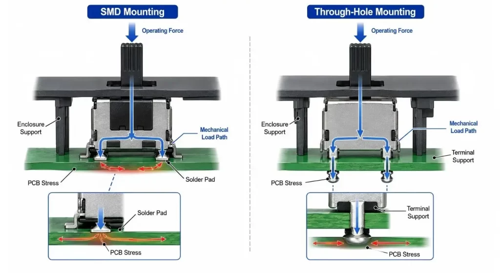
The size of the footprint must be the same as the terminal size, terminal locating features and soldering method. Through-hole terminals may be used to offer mechanical support while a small 4-pin SMD slide switch can be appropriate for low-profile and space-constrained PCB assemblies. The selection of the correct choice is based on board layout, operating force, assembly process and enclosure support.
Avoid placing any heavy parts, tall connectors or stiff cable on the path of the actuator. The switch should not be used as the alignment of two poorly matched assemblies.
| Design Input | What to Confirm | Risk if Ignored |
| Operating direction | Vertical, top-access or side operation | Wrong switch orientation |
| Actuator geometry | Height, width, travel and position | Poor access or panel rubbing |
| Circuit function | Pole, throw and maintained positions | Incorrect signal switching |
| PCB interface | Footprint, keep-out area and locating features | Assembly interference |
| Mounting method | SMD, through-hole or supported panel mounting | Weak solder joints |
| Enclosure interface | Slot size, wall thickness and tolerance | Binding or excessive play |
| Electrical conditions | Voltage, current and signal type | Contact instability |
| Validation plan | Cycling, vibration, temperature and contamination | Early field failure |
Select Size Only After Checking Access
However, miniaturization can be of assistance only if the switch is still practical to assemble and operate.
A micro slide switch is suitable for portable electronic applications, control boards and compact devices. But a smaller body also results in less tolerance for enclosure – and manual soldering and rework.
Ask for dimensional drawing prior to laying out PCB. Not only the catalogue width but also body outline, the position of the actuator in each state, terminal coplanarity, keep out area and assembly direction.
Understand that the input is associated with the output in a function
The users make their decision about a slide switch, without knowing its contact resistance.
The clear detent indicates that there has been a change in state. If the force is not sufficient, the accidental movement may occur, if the force is too large, it will increase the stress on the mounting and make the small control feel rough, so that the stress on the mounting will be greater. Poorly built switches can also be caused by side play.
Evaluate samples inside the actual housing. A hand-feeling smooth switch might feel otherwise after being soldered, aligned on a panel and used over and over.
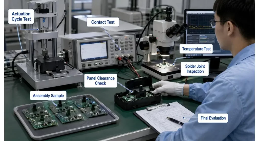
Use the ASSEMBLY VALIDATE command to validate the Complete Assembly
Only loose component is tested and many practical failure are not found.
Rotate the switch in the housing, and test contact stability, actuator wear, rubbing on the panel and solder joint movement and recognition. If dust, vibrations, cleaning agents, or temperatures changes are a concern where the product will be used, test the product in these conditions utilizing the final mounting arrangement.
Discuss the production process too. The thousandth switch may or may not look like the approved sample depending on the influence of terminal forming, moulded-body consistency, contact assembly and final inspection.
Conclusion
A vertical slide switch should be chosen as part of the user interface (not just as a standalone electrical component), enclosure and PCB.
Firstly define the operating direction. After that, verify the accessibility of the actuators, circuit logic, footprint and soldering support and actual assembly tolerances. With a small switch, a few careful checks before release of any PCB can save a small switch from becoming a surprisingly expensive redesign.
FAQs
Q1. Explain what is a vertical slide switch?
It is a type of slide-operated electrical switch which is designed to be operated vertically or by way of the top in a product.Actual meaning to be taken from its mounting and actuator drawing.
Q2. Does a vertical slide switch = a right angle switch?
Not necessarily. Normally, a right angle type switch is parallel to the edge of the PCB whereas the vertical type can be accessed from above or move perpendicular to the PCB.
Q3. What is the best option for mounting: SMD or through-hole?
SMD is suitable for small size automated PCB assembly, or through-hole terminals can have more mechanical support. Expect operating force and enclosure should be taken into consideration too.
Q4. What type of information is necessary prior to asking for a sample?
Include circuit diagram, orientation of the PCB, direction of the actuator, available space, thickness of the panel, electrical load, method of soldering and anticipated life.
Q5. Why could it be necessary to test the switch inside the enclosure?
The housing can alter the access to the actuators, friction and applied force. Assembly level testing tests issues which are not apparent from a loose switch bench test.
