





6 Position Slide Switch: Make Six States Easy to Use
It is easy to get the 6 position slide switch, but when the team begins to identify the 6 positions, it gets complicated.
Is it 6 fan speeds, 5 fan speeds (including OFF), 6 audio inputs or 6 service modes? If the circuit goes off when it switches between positions, should one of the contacts stay on or should it go off as the other one is switched?
The following questions should be part of the initial design meeting. A six position mechanism is capable of 6 stops, but cannot determine what those stops are.
Make sure “6 Position” is a correct requirement
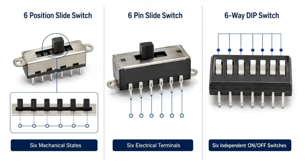
A 6 position slide switch is a switch with 6 mechanically selectable positions, it is all in one travel path. This is not the same as a 6-pin switch, where the number of terminals is the only thing that is specified.
For instance, the switch Hanxia offered in the photo is 6 pin slide switch, but it does not show that it has 6 position to be selected for Fan-speed, Fan Mode and Fan-function.
Also different in comparison with a 6 position DIP switch. A six-way DIP package is a six independent ON/OFF package which can be configured to many binary combinations and is normally set by a six-position slide switch.
It should be clearly stated on the specification beforehand what that distinction is, before requesting samples.
Create the Six-State Map FIRST
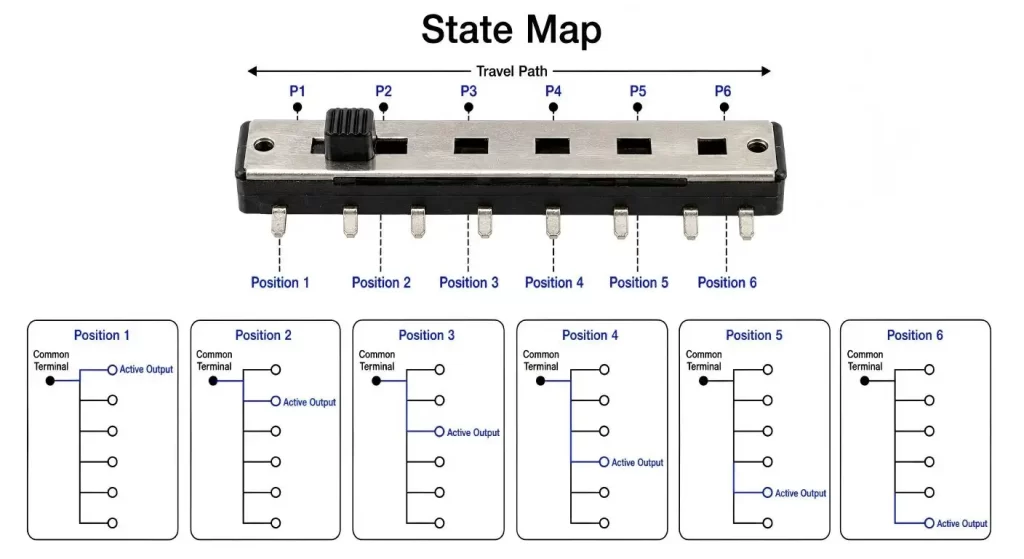
Write down what occurs electrically at positions 1-6 before deciding the body size or the length of the actuator.
A state map that is useful will identify:
· which terminals are connected;
· which output is active;
· whether OFF is one of the six positions;
· whether unused terminals float or connect to a reference;
· what the product displays to the user;
· what the circuit should do while the slider is moving.
This can frequently show that the project doesn't require 6 separate outputs. Depending on the function, a coded contact pattern or fewer switch poles, or a resistor ladder, can do the same job with less wiring.
For the larger slide switch range there are variations in the slides as well with respect to types of poles, throws and mounting.
Choose the action that takes place between the poses
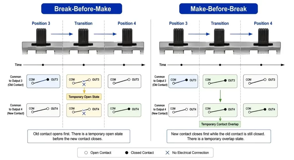
The secret of a multi-position switch is the little time interval between two detents - between two positions.
Break before make: Disconnects current position before connecting next position. That can make it difficult for two outputs to be active simultaneously, but also results in a short circuit.
Make before break is when contacts overlap during moving. This can provide continuity, but can temporarily provide continuity across adjacent circuits. That would be inappropriate if two outputs are never to be allowed to operate at the same time.
If it's a digital input, it can also record multiple quick changes in the position of the contacts. Filtering of this behavior is possible with firmware; however, a software solution cannot be expected to remedy an inappropriate contact sequence.
A simpler two circuit transfer (SPDT slide switch) is shown. Six states are no different, in terms of contact-logic discipline, than moving to six states.
Include the movement of Every Detent as a means to make it different.
A 6 position selector should let the user know that the actuator has got to a valid position.
Weaker detents can cause the slider to halt in between positions. Too much force could result in missing a setting or in pushing the enclosure rather than the actuator. They actually will feel damaged in one position due to the uneven operating force even when the contacts are still working.
The entire trip is important as well. Six labels in such a small area may be a little tight, and each position is a bit more difficult to select. Longer travel means better separation but more space and cost of the panels and PCB's.
Test switch with the intended knob, panel slot and finger access. The loose component does not necessarily have the same feel as the completed control.
Align Panel Labels To Electrical State
Errors in which the control is placed at a single wrong position are frequent errors in 6-position controls.
The drawing of the PCB may be numbered 6, 5, 4, 3, 2, 1 while the enclosure may be numbered 1, 2, 3, 4, 5, 6. Mirrored footprint or reversed assembly direction or actuator (seen from a different angle) can cause the product to run in reverse.
The safest approach is to define one reference view and to use this view for:
· the circuit table;
· PCB footprint;
· mechanical drawing;
· panel artwork;
· inspection instruction;
· software state names.
Never use words like “left position” without indicating which side of the manufactured product is being observed.
| Design Item | What to Define | Risk if Unclear |
| Six states | Function assigned to positions 1–6 | Incorrect product behavior |
| Contact map | Connected terminals at each position | PCB and switch mismatch |
| Transition type | Break-before-make or overlap | Open circuit or output conflict |
| Position spacing | Total travel and detent pitch | Difficult state selection |
| Reference direction | Viewing side and position numbering | Reversed labels or footprint |
| Electrical load | Voltage, current and load type | Contact overheating or wear |
| Mounting interface | PCB footprint, actuator and panel slot | Mechanical interference |
| Validation | State, force, cycling and alignment checks | Inconsistent middle positions |
Test Electrical Load at each Position
A multi-position selector is not necessarily suitable to switch six power levels directly.
The contact ratings are a function of the voltage, current, load type, load switching conditions. Motors, lamps and capacitive loads may have a starting or switching current that is higher than the steady state value.
The slide switch should only be used to supply a low current control signal in many products, and a transistor, relay or controller must be used to switch the load. Hanxia's slide switch for power control has a rating of 50 mA, 12 VDC for the specific model referenced, which is why it is important not to choose the part based on the product type but to verify the rating of the specific part chosen.
Verify existing pathway for six positions and transitions.
Allow PCB to have sufficient space for six states
The greater the number of positions, the greater the length of the body and the greater the number of terminals or the more complicated the internal contact plate.
Inspect entire footprint, not a 2-position switch drawing. The number of the terminal, position of locating pegs, position of actuator centreline and body overhang must conform to the selected part.
Actuator travel and access for inspection should not be obstructed by nearby components. Another undesirable routing practice is to pass multiple switched signals under the switchboard.
Refer to manufacturer's dimensional drawing and pin diagram. Hanxia has a download centre for technical and product materials, the drawing of the specific model still needs to be confirmed before the board is released.
Test All Six Positions, Don't Just Test End Stops
Position 1 and position 6 is too little.
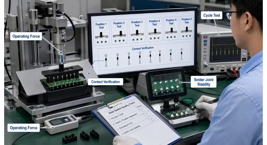
Check all detents for contact state, operating force and alignment. Next go over the entire range of motion several times and see if any midrange positions appear to be more worn or contact is inconsistent.
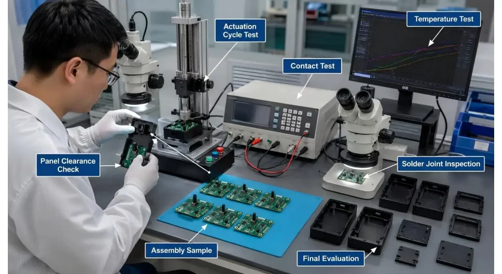
Consideration should be given to include the following in assembly testing:
be able to spell the correct state at each of the 6 stops;
· correct state at all six stops;
· transition behavior;
· panel-label alignment;
· contact resistance;
· actuator play;
· solder-joint movement;
· repeated cycling;
· vibration or accidental movement where relevant.
To make the interface simple a 6-position switch is often used. It must not provide six possibilities for "not knowing".
Conclusion
The best 6 position slide switch is NOT the switch with the most terminals or smallest body.
It is the one in which the six mechanical stops are obviously related to six product states. Please specify the following parameters before requesting a sample: State map, contact sequence, detent spacing, panel orientation and electrical load.
With those details corrected, it becomes a lot easier to select the footprint and actuator, and the six settings are easy to understand from schematic to user's hand.
FAQs
Q1. What is the meaning of 6 position slide switch?
A mechanically controlled 6-position indexed actuator selector. These positions result in a well-defined contact state or circuit function.
Q2. Does a 6 pin slide switch equal a 6 position switch?
The number printed on 6 pins represents the number of mechanical states available (6 positions) while the number of printed on 6 terminals represents the number of quantities (6).
Q3. What is the difference between this and a 6 position DIP switch?
DIP package – 6 separate binary switches. A 6 position slide switch is used to switch between six states, normally.
Q4. What is “break before make”?
An open existing contact is the one that is in front of the closed new contact. It won't overlap, but will cause a short lost contact state when moving.
Q5. What information should be supplied when asking for a quote?
Include the 6 position circuit map, electrical rating, direction of actuator, how to mount, PCB space, size, operating force and expected life.
