





Tact Switch Protect Guide: Stop Button Failures Early
A tact switch can last for thousands of times on the engineer's workbench, and fail early after the enclosure is built.
This isn't often the only cause. A keycap is pressed at an angle, the housing permits excessive key travel, cleaning solution gets on the metal dome, or static electricity is transferred from users fingers to the controller input.
Tact Switch Protect Design Starts on the Outside. Trace the flow from the finished button to the PCB, of the force and of the contaminants and electrical disturbance.
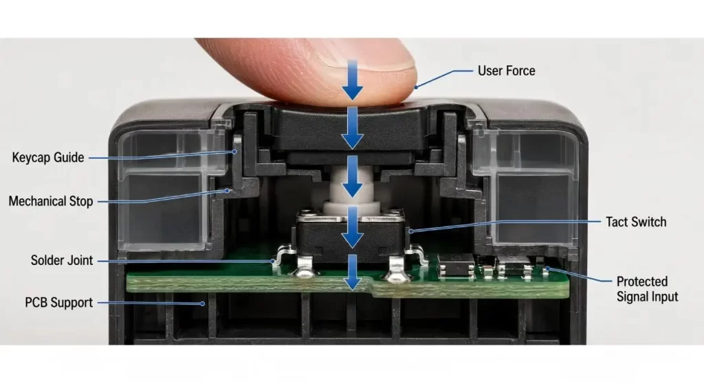
Protect the Switch From the Keycap
This is the official method to safeguard the Switch.The outside button should push the actuator down and self release without rubbing on the enclosure.
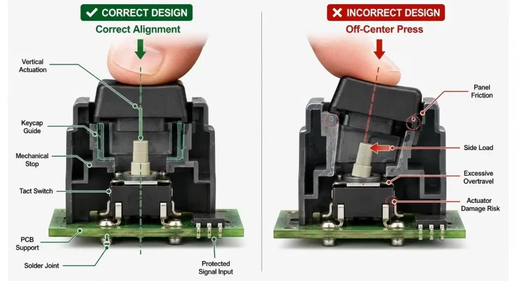
When there is a slight deviation from the alignment, side load is created. An oversized opening permits the button to tilt and an opening that is too small forces the friction of the housing to be a component of the operating force. Both conditions are not seen if the loose switch is hand tested.
Install a mechanical stop (enclosure or keycap). The switch should close the circuit and it should not take the brunt of the force of a hard press when it is activated.
The tact switch range is available in various sizes, heights, force requirements and mounting options. These dimensions need to correspond to the full button stack and not just be based on PCB space.
Wearing a cap for the correct purpose
To enhance grip, to soften the finger contact and to make less dust or splash reach the actuator a silicone cap can be used.
But, a cap isn't necessarily a watertight seal. Water is able to flow around the cap, through the panel opening or under the PCB.
Hanxia's 6×6 tact switch with rubber cap provides an optional silicone cap for ergonomics and a bit more dust/splash protection, but this is not a complete IP seal.
The cap is not the whole environmental-protection solution – it is simply part of the enclosure interface.
Prevent User from coming into contact with the Solder Joints
Mechanical load path is established with each press.
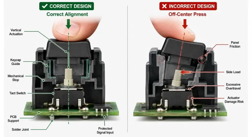
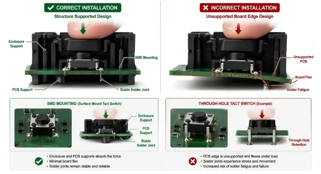
The force travels through the keycap, housing support and switch body and is supported well. The SMD pads are the only structures to withstand repeated presses with a poor design.
Test to see if the PCB flexes under the button. Care should be taken to ensure that unsupported board edges are away from frequently touched controls, and that no attempt is made to correct PCB/enclosure misalignment using the switch body.
A proper PCB tact switch can be installed by SMD or THD, and there are various operating force and forms of the actuators. Full assembly requires mechanical support and through-hole terminals can contribute retention.
| Protection Area | What to Confirm | Common Failure |
| Keycap alignment | Vertical force and free return | Side-loaded actuator |
| Overtravel control | Mechanical stop after actuation | Dome fatigue or damage |
| PCB support | Board stiffness and enclosure support | Cracked solder joints |
| Electrical load | Voltage, current and load type | Burned or unstable contacts |
| ESD control | Grounding, trace route and protection device | Controller input damage |
| Environmental seal | Dust, splash, washing and condensation exposure | Contact corrosion |
| Assembly process | Placement, reflow, cleaning and coating | Heat or liquid damage |
| Validation | Edge press, cycling, ESD and environmental tests | Bench sample passes, product fails |
Avoid making the Tact Switch Drive the Load!
Most tact switches are designed to switch a low current momentary signal, NOT to directly power a motor, lamp or solenoid.
If the product is used to control a large load, use the tact switch to signal a microcontroller, a transistor, a MOSFET or a relay driver. If the load is an inductive load, appropriate suppression must also be provided to prevent the switching node from coming into contact with voltage surges.
For a specific part and load type, contact ratings must be taken. A switch that could be used for logic input may fail prematurely if it is called upon to switch a higher or very capacitive current.
Contact bounce can be handled with a firmware or an RC network. Debouncing is beneficial for better signal interpretation, but will not help with an overloaded contact.
Give Static Electricity a Better Route
A button that is accessible to the user may be an ESD entry point.
Noise or static can be conducted from a metal keycap, switch frame, exposed panel opening or exposed PCB trace to the input of a sensitive controller. This switch in itself is not necessarily system level ESD protection.
Minimize the input trace on as practical as possible, establish a grounding path and locate the needed protection close to the sensitive circuit. Hanxia's mini tact switch for digital cameras specifically suggests the switch mechanism to be protected with PCB level ESD protection and the perpendicular actuation.
The assembled product geometry must be tested as ESD follows the product not just the schematic.
Be sure to separate Washable, Sealed and Waterproof
These descriptions should NOT be used interchangeably.
A process sealed switch might be designed to withstand flux cleaning following the soldering process. The waterproof model may be more resilient to water or rain and dust. But exactly where the test boundary is still matters.
If washing or conformal coating of the PCB is foreseen, determine if liquid can seep around the actuator. A standard open switch should not be cleaned or coated with cleaner or coating.
A waterproof tactile switch may be a better starting point for exposed controls, but a panel opening, gasket and complete enclosure are still a part of the protection system.
Click From Preload & Click Overtravel Protection
A Tact Switch relies on a metal dome or other type of mechanism for its snap action.
If this external keycap lies too heavily on the actuator, the switch might not be completely unloaded. The button may have a soft feel, it may press too soon or it may not retract properly. Over-travel can cause wear or wearout of the dome or cause internal parts to be distorted.
Provide controlled free clearance between keycap and actuator. Then position the enclosure stop so that the switch is at the stop position desired but will not be given excess travel.
Inspect this at maximum and minimum assembly tolerances. A design which is just nominal in size is not production ready.
Be sure to protect the Switch during assembly
Damage to components may start even prior to the customer pressing the button.
Pick and place nozzles should touch the desired pickup surface, but not the edge of the actuator. Reflow conditions have to comply with the specification of the model chosen. When manually reworking, do not heat for long periods of time and never push side to side on a warm switch body.
Following soldering, check wetting of terminals, body position and freedom of movement of the actuator. A switch that has a slight tilt or bend can pass an electrical continuity test, but bind against the keycap once it is fully assembled.
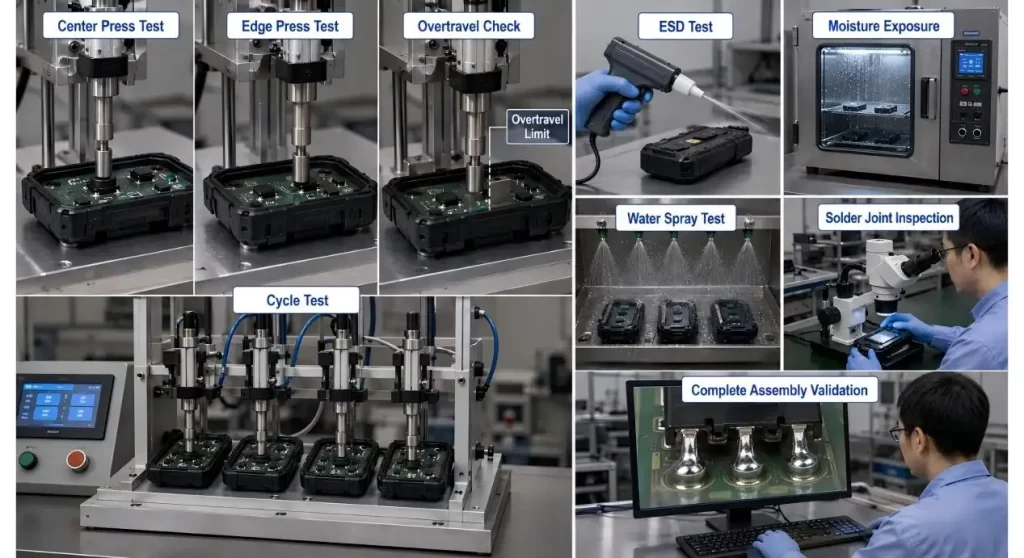
Press the Complete Button Stack button to test the button stack
Avoid just pressing the centre of the switch with the test probe to qualify the switch.
Utilize production representative PCBs, keycaps and housings. Test centre presses, edge presses, rapid presses and press firmly on enclosure stop.
The validation plan should include:
- Operating force and tactile feel;
- Return and alignment keycap;
- overtravel control;
- Contact bounce and continuity;
- Motion of PCB and solder-joints;
- ESD exposure;
- humidity, dust or splash conditions;
- operation following the temperature and life cycling.
Check failed samples before replacing. Normally, an examination of the actuator edges will show if the problem was due to the switch, enclosure or assembly process and there will be no need to open the device.
Conclusion
When protecting a tact switch, you have to do more than select a long life switch.
The enclosure should direct the user's application of force, restrict the range of motion and prevent contamination. The PCB must provide the switch with mechanical support, electrical protection and prevent the switch from being asked to power an inappropriate load.
If the keycap, switch, PCB and enclosure are tested as a complete unit, such a small button cannot be a recurring warranty issue.
FAQs
Q1. What is meant by protection of Tact Switch?
It is related to mechanical, electrical and environmental solutions to prevent early failure of tact switches. These are such as alignment, overtravel stops, sealing, ESD control and correct load handling.
Q2. If a rubber cap is placed over a tact switch, is the switch waterproof?
Not necessarily. It can minimize dust and splash exposure but, complete water protection is dependent upon the construction of the switch and enclosure seal.
Q3. How to avoid ‘overtravel' of the tact switch?
Install a hard stop on keycap or enclosure. If the switch has been actuated there should be excessive pressing force at the stop.
Q4. Is an ESD protection required for a Tact switch?
System level ESD protection might be required close to the controller inputs where they are accessible to the user. The design required is dependent on the enclosure, the grounding compliance product and target.
Q5. If an SMD tact switch is to support the total button force?
No. The enclosure and PCB structure should be designed in such a way that the solder pads are not the only mechanical load path for repeated operation.
