





Horizontal Rocker Switch: Make Left and Right Mean Something
A horizontal rocker switch can be very apparent on a drawing. Press left side for one state press right side for other state.
Things begin to get confused after a few teams get in the mix. The electrical drawing puts the ON terminal on one side; the enclosure artwork puts the ON symbol on the other side, and the assembly operator puts the switch in, after rotating the panel.
The switch moves but still rocks correctly. The product is simply giving the user the false information.
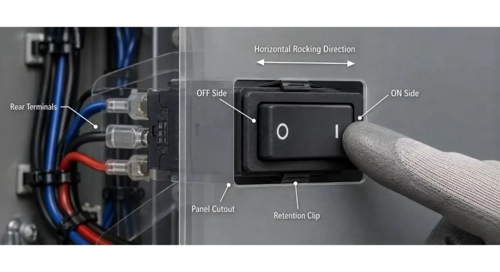
Define “Horizontal” in the user's view
Horizontal should refer to the end result of the control as viewed by the user, NOT the "open switch on a desk.
Make sure that the value of the actuator's rock left to right, the long axis of the actuator is horizontal and make sure which side is considered the front. On the same drawing, also show the directions of the PCB, panel and terminal.
Various rocker switch shapes, circuit configuration, illuminated types and mounting configurations are available. These comparisons are helpful only once a certain viewing direction of the product is determined.
Do not use terms like “terminal 1 – on the left”, unless viewing side is clearly indicated on drawing.
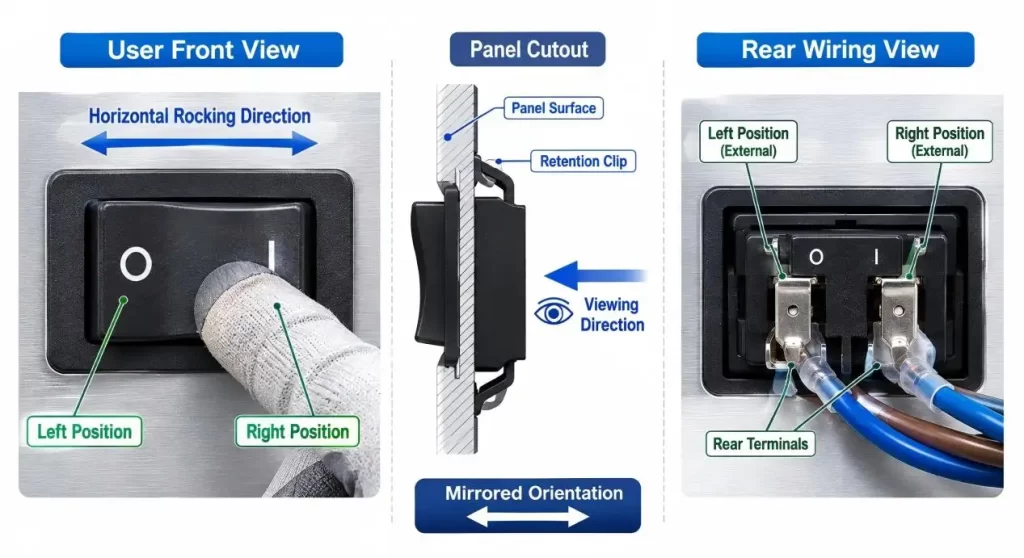
Provide a clear meaning for each side
A simple ON/OFF control should have the status known to the user prior to starting up the equipment.
Sometimes, such as with control strips, the operation will be horizontal, meaning that several switches are lined up horizontally. It can also be effective in situations where space is limited for vertical panels. Left and right however do not necessarily represent a direction of electricity.
Include permanent actuator I/O symbols, text or icons on the surrounding panel or actuator. If the product is sold in other countries, the symbols are typically more successful than words alone.
The product team will need to coordinate a product switch position, wiring schematic and printed legend in this case for a simple two-state interface, with a compact 2-position rocker switch.
Click on Circuit Before the Appearance
A two position actuator doesn't indicate the internal workings.
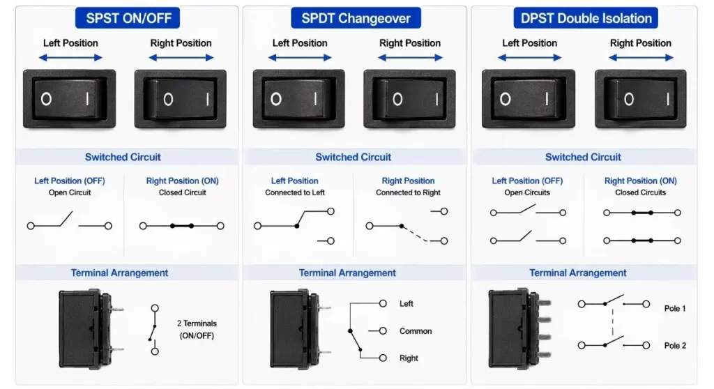
SPST is typically used for a simple ON/OFF, single circuit application. DPST can isolate two conductors together or a SPDT or DPDT can route the circuit or reverse a low voltage load (if designed for it).
The decision should be made based on the schematic and isolation requirement/failure behavior, NOT just based on the number of terminals.
Hanxia's rocker switch for power control applications has a certain AC rating and is a four terminal type. The specification should be used only on the exact model and should not be used on a similar model with the same body.
| Design Input | What to Confirm | Risk if Ignored |
| User-facing direction | Left/right action and front viewing side | Reversed operation |
| Circuit function | SPST, SPDT, DPST or DPDT | Incorrect switching logic |
| Load condition | Voltage, current, inrush and load type | Contact arcing or welding |
| Position marking | I/O symbols, text and orientation | User selects the wrong state |
| Illumination | Voltage, polarity and indicator purpose | Lamp does not match output |
| Panel interface | Cutout, thickness, corner radius and retention | Loose or deformed switch |
| Terminal layout | Tab type, spacing and harness direction | Wiring interference or strain |
| Validation | Load, temperature, retention and life testing | Sample works but assembly fails |
Not Only the Current Number, But Also the REAL LOAD
The printed current rating is just the start of a review of electrical parts.
Heaters and other resistive loads are different than motors, transformers, lamps and capacitive power supplies. A motor may have a high starting current or a power supply may have a short inrush current every time the switch is closed.
When a switch is selected that is not approved to this type of load, the contacts may arc, weld or wear out prematurely under normal running current which may seem acceptable.
The site's 12V rocker switch guide describes the necessity of considering the current in addition to voltage, and of considering the pole configuration and environmental rating as well.
If possible, use a relay or an electronic driver to allow the rocker switch to operate a lesser signal, rather than switching a heavy-load directly.
Don't share Illumination with other circuits
In a dark room an illuminated actuator can be used to indicate the position of the switch, or to make sure the equipment is turned on.
That is another function.
A dependent indicator is only illuminated if the switched output is "on. An independent indicator can display location, stand-by status or other system status and have their own terminals.
Prior to installing wiring, verify:
- Use of LED or neon lighting;
- indicator voltage;
- polarity where applicable;
- shared or separate neutral/ground;
- If the lamp has a switch position indicator or output power indicator.
Never guess on the number of pins as the light circuit. Get a detailed wiring diagram.
Turn the Switch On for the Panel to Hold
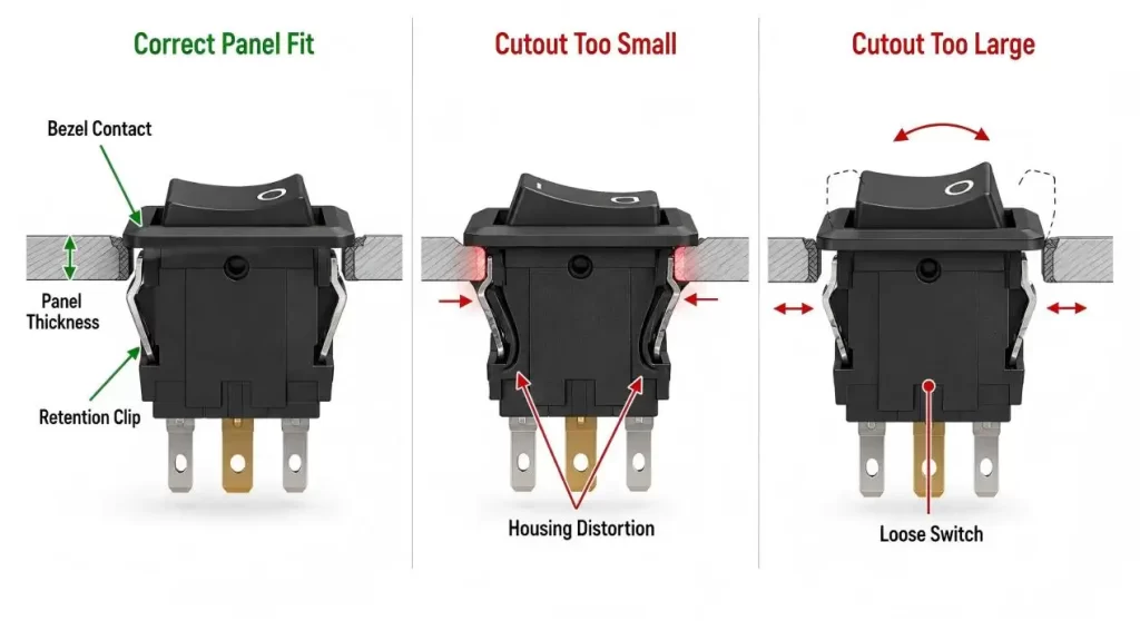
A snap-in rocker switch is a switch that relies on the panel cutout, wall thickness and retaining tabs.
A too small opening may cause the housing to be deformed, causing the rocker to become stiff. If it is too large, the switch can be moved while it is being manipulated or the wiring harness can pull it out.
Inspect corner radius, burrs, and paint thickness and moulding draft. When the panel is produced by different suppliers / tools, a nominal rectangular hole is not sufficient.
A soft-touch rocker switch for industrial machines provides different actuator, mounting, sealing and terminal options for equipment that is used with gloves, vibration or washdown. Even the highest sealing performance is still dependent upon proper installation with gasket compression of the panels.
Discuss how to route the Terminals Without Loading the Housing.
The orientation of the panel may also affect the orientation of the wires exiting the back of the switch (horizontal).
Space must be provided for insulated receptacles and removing tools for quick-connect terminals. Constant flexing of harness bends can constantly pull on terminals, or an over-sized connector can come in contact with the enclosure or another live connector.
Strain relief and ensure harness is out of the way of the moving retaining tabs. Make sure that the terminal orientation is correct before the tooling is frozen; if the switch has been turned around when wiring, it is possible the ON/OFF direction facing the user is reversed.
Inspect where mains voltage is involved for creepage, clearance and barriers.
Prevent Accidental Operation
A wide rocker provides ample space to operate it, but can also be accidental to press.
Think about the handles, packaging foam, cleaning cloths and objects that come into contact with the control panel. Where there is a state change that is different from what is expected, a raised bezel, recessed mounting position and/or firmer actuator may be appropriate.
A normal rocker switch should not be offered as an emergency-stop switch! Safety functions must be provided with the proper circuit design, product type and approval.
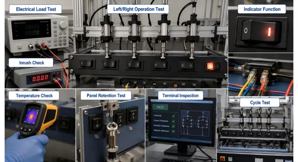
Test Switch in Final Orientation
Bench continuity testing can't tell if the installed switch is appropriate to the user.
Create panel of production and test:
- left and right accuracy of states;
- legend orientation;
- operating force;
- panel retention;
- terminal access;
- indicator wiring;
- temperature rise;
- Often changing under load to be repeated;
- Vibration resistance or resistance to accidental contact.
Apply dimensional drawing/wiring information of the exact part. The download center of Hanxia offers various product resources; nevertheless, the model and revision to be selected should be confirmed before the release of products.
Conclusion
A horizontal rocker switch works well when there is a mechanical and electrical match-up, and the visual message, which is the state the switch is in.
Start with a definition of the front view. Next compare the circuit, load, illumination, panel cutout and the direction of the panel terminals. When the entire control panel is built, testing will ensure that even a minor orientation error will not escalate into the problem of tooling, wiring or user-safety concern.
FAQs
Q1. What is a rocker switch?
A rocker operated switch that's set up to slide or look left-to-right when completed. The exact orientation should be determined from the user's point of view.
Q2. Is the left side the only time they are OFF?
No. Internal circuit, direction of installation and cable routing are crucial for the state of the state. Make sure the symbols are clear and check the final product for correctness.
Q3. Is it possible to use a rocker switch to directly control a motor?
If the motor load and its starting current are rated on the exact switch. If not, then employ a proper relay or electronic driver.
Q4. Why do illuminated rocker switch have 3 or more terminals?
Other terminals might provide the indicator lamp or for a different pole-and-throw configuration. Don't guess the wiring based on the number of pins, follow the exact wiring diagram.
Q5. What information would you need to get for a quotation?
State Circuit function, voltage, type of load, panel cutout, mounting orientation, terminal style, illumination requirement, environment and expected operating life.
