





Sliding Door Limit Switch Specifications Buyers Should Compare
A Sliding Door Limit Switch determines if a door is in a fully open, fully closed, or any intermediate position and sends the relevant information to a controller, motor, alarm, or safety interlock.
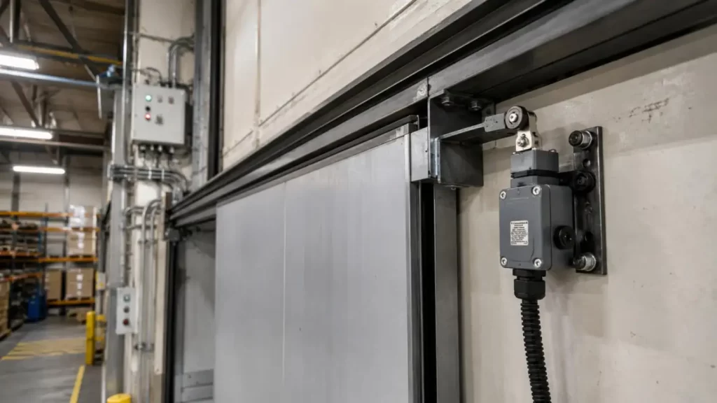
Switches that may look similar could have differences in multiple areas such as service life, environment protection, and electrical rating among others. If a Sliding Door Limit Switch is selected poorly, it could lead to signals that are unstable, stopping positions that are incorrect, premature service, or faults in the control system.
To ensure that procurement is done reliably, buyers must specify the structure of the door, the service of the circuit, the frequency of operation, the available installation space, and environmental factors and only then can a comparison of products be made.
What Is a Sliding Door Limit Switch?
A Sliding Door Limit Switch is a device that has an electromechanical position detection feature. It has a plunger, lever, or roller that makes contact once a moving door, bracket, or cam hits a predetermined position.
The switch is able to:
•Indicate that a sliding door has reached a designated position
•Command a motor or controller to stop
•Initiate a reverse motion, safety action, or response
•Stop the sliding door from moving beyond a set limit and stop
•Support door interlocking and access-control functions
Some of these are found in an automatic entrance door, industrial safety doors, doors found in elevators and warehouses, guards for machinery, and doors found on transportation platforms.
Key Sliding Door Limit Switch Specifications to Compare
1. Contact Configuration
The contact arrangement determines the form of communication of the switch with the control circuit.
The most common arrangements are:
•Normally Open (NO): The circuit is closed with the actuation of the switch.
•Normally Closed (NC): The circuit is opened with the actuation of the switch.
•Changeover Contact: The COM can be connected to either NO or NC.
•SPST: Able to control a single electrical circuit.
•SPDT: Changeover switching for control logic.
Sliding Door Limit Switches are designed to meet the input and fail-safe logic of the control system. It should be understood that buyers cannot assume that similar appearance termination perform the same function.
2. Rated Voltage and Current
Electrical ratings should be reviewed according to the actual load rather than the highest value shown on a datasheet.
Buyers should compare:
•AC and DC voltage ratings
•Maximum switching current
•Resistive and inductive load ratings
•Minimum current requirements
•Motor, relay, and controller-input compatibility
A switch used for a low-current control signal may require different contact materials from one switching a relay or motor circuit. Inductive loads can also create electrical arcs that shorten contact life.
3. Operating Force and Travel
The switch's activation function is dictated by the mechanical operating parameters. The main parameters are:
•Operating force
•Travel
•Differential travel
•Release position
The operating force directly influences the impact on the mechanism. Variation in position of the switch is countered by sufficient overtravel. Uncontrolled travel and overtravel can lead to damage of the actuator and the mounting structure.
For precise positioning, the Sliding Door Limit Switch should be analyzed along with door speed, the angle of the actuator, the mounting tolerance, and anticipated mechanical movement.
4. Mechanical and Electrical Life
•The terms "mechanical life" and "electrical life" are used to describe two different concepts.
•Mechanical life is the number of operations possible without loading the switch electrically.
•Electrical life is the number of operations possible at a defined voltage, current, and load.
For the purpose of safety, doors operating at high frequencies should be designed with an emphasis on reliable and repeatable electrical life specifications, actuation, and contact resistance, rather than a high mechanical life.
5. Housing, Terminals, and Mounting
Operational and installation compatibility of the Switch is determined by the housing and terminals.
Buyers should compare:
•Housing dimensions
•Mounting-hole distance
•Terminal position and direction
•Screw, solder, quick-connect, or wired terminals
•Wire length and connector type
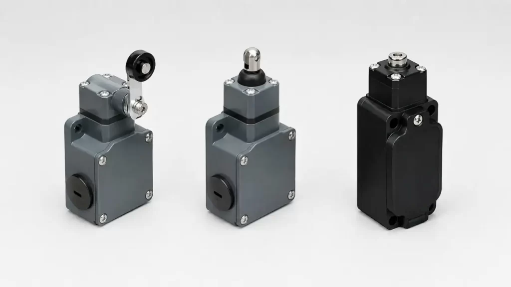
•Plunger, roller, or lever actuator
•Required mounting orientation
A compact housing alone does not guarantee installation compatibility. The actuator must contact the moving door at the correct angle without excessive side loading.
Environmental and Safety Specifications
A Sliding Door Limit Switch should be selected for its actual operating environment.
Key conditions include:
•Dust and water exposure
•Working temperature
•Humidity and condensation
•Mechanical vibration and impact
•Housing flame resistance
•Corrosion resistance
•Outdoor weather and ultraviolet exposure
An indoor commercial door may use a standard housing, while an outdoor industrial door may require sealing, corrosion-resistant metal parts, and stronger vibration resistance.
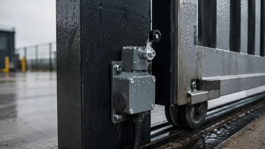
Ingress protection ratings should be verified against the complete assembled switch, including terminals, cable outlets, and connectors. Certification and compliance documents need verification for the particular model and target market.
Variations in Door Position Sensors
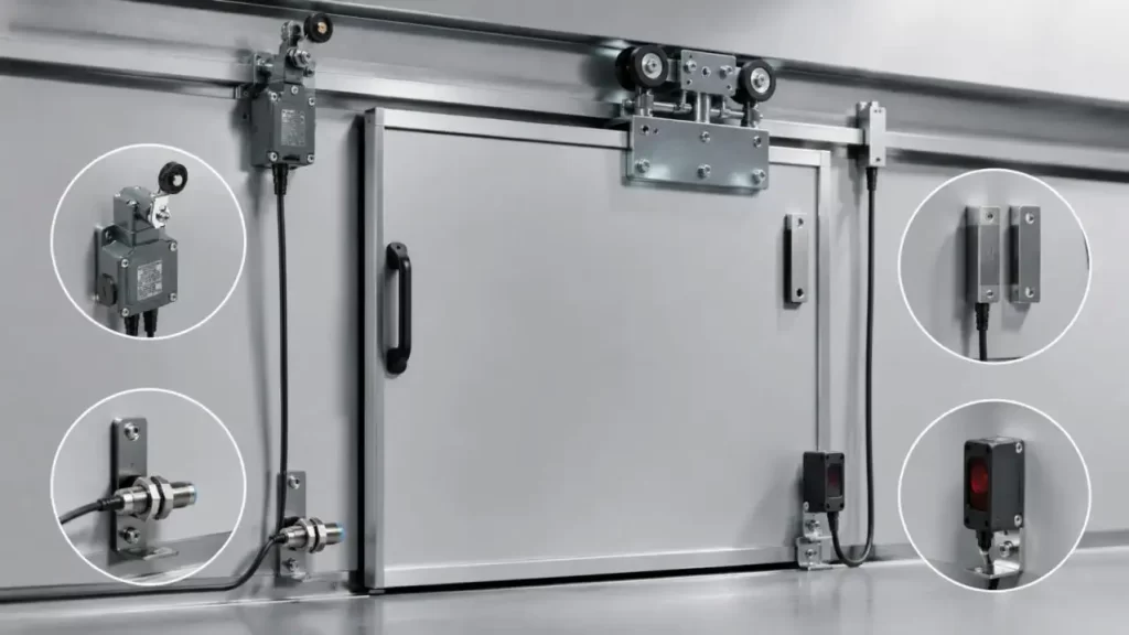
| Product Type | Operating Method | Primary Benefit | Typical Application | Main Limitation |
| Mechanical Sliding Door Limit Switch | Actuator is switched by door contact | Defined switching and easy wiring | Industrial and automatic doors | Mechanical contact will wear |
| Magnetic Reed Switch | Contact is made by a magnet | No mechanical contact | Low power and lightweight doors | Affected by magnet's distance and orientation |
| Inductive Proximity Sensor | Detection of a metal target | Non-contact and frequent actuation | Industrial automatic doors | Requires power and higher overall system cost |
| Optical Sensor | Detection using light | Very quick response | Used for door control and safety detection | Operational disturbances from dust and light |
If the installation requires clear physical confirmation and control, a Mechanical Sliding Door Limit Switch is often the best choice. Non-contact sensors will reduce wear, but they will be more complex to control and require power, alignment, and design integration.
Models Within the Same Type
| Comparison Area | Basic Configuration | Enhanced Configuration | Procurement Impact |
| Actuator | Direct plunger | Roller or lever | Adjusts contact angle and installation |
| Contact Structure | NO or NC | SPDT changeover contact | More flexible control options |
| Housing | Standard plastic | Heat-resistant or flame-retardant materials | Better suited for harsh environments |
| Terminals | Solder terminals | Quick connector or custom wiring harness | Changes the efficiency of integration |
| Protection | Open structure | Sealed or dust-resistant structure | Establishes suitability for industrial or outdoor use |
| Service Life | Standard contacts | High-life spring and contact materials | Provides longer intervals to maintenance |
Vertical comparisons of Sliding Door Limit Switch models should focus on materials, contact performance, actuator precision, sealing, and life expectancy. Unit price alone does not reveal installation cost or long-term reliability.
Common Procurement Mistakes
❌Selecting a switch only by housing size while ignoring operating travel
❌Treating mechanical life as equivalent to loaded electrical life
❌Failing to confirm NO, NC, and COM terminal logic
❌Ignoring the impact of door speed on the actuator
❌Approving a generic sample without installation testing
❌Comparing unit price without considering assembly and maintenance costs
❌Using certification documents that do not cover the actual model
Closing Words
Share your door drawing, mounting dimensions, electrical ratings, actuator requirements, terminal layout, operating frequency, and application environment with Hanxia. Our team can support structural design, tooling, sample development, automated assembly, functional testing, and dimensional inspection.
Founded in 2014, Hanxia operates a 5,600-square-meter facility with more than 90 employees and multiple automated production lines. Get in touch with Hanxia to review the configurations of Sliding Door Limit Switch that can be applied, then finalize the design after production-equivalent installations and working samples are produced.
FAQs
Q1. What is a Sliding Door Limit Switch?
A Sliding Door Limit Switch indicates to the control system, drive motor, or safety system, the positions of a moving door that is fully open, fully closed or any other designated position along the travel.
Q2. Which type of contacts should customers select?
The appropriate type is determined by the application control circuit. The most frequently selected contacts are Normally Open, Normally Closed and SPDT changeover contacts with COM, NO and NC designations.
Q3. What do voltage and current ratings signify and why are they important?
Ratings signify the load limit a switch will control with safety. Buyers should pay attention to the ratings for AC or DC, the switching current and whether the load is of a resistive or an inductive type.
Q4. What is the distinction between mechanical and electrical life?
Mechanical life is the number of operations that a device can sustain without making an electrical circuit. Electrical life is the number of switching operations that a device can perform under given voltage, current and load conditions.
Q5. How does travel of an actuator affect the positioning of a door?
The concepts of pre-travel, the position of the limit switch when the door is in the normal operating position, overtravel, and release travel define the possible range of travel for a sliding door limit switch. The actuator travel may result in incorrect stopping or overtravel which may cause the door to bind.
