Tactile Switches in Microcontroller Projects: The Interface Guide
Tactile switches are the standard "user input" mechanism for microcontroller projects, allowing users to send momentary signals to devices like Arduinos, ESP32s, or STM32s. In these systems, the switch acts as a bridge between the physical world and digital logic, converting a mechanical press into a binary voltage change (0 or 1) that the processor can detect and act upon.
While they appear simple, successfully integrating a tact switch requires understanding three distinct layers: the physical pinout, the electrical circuit (handling voltage states), and the software logic (managing signal noise). This guide covers the entire workflow, ensuring your button press triggers the exact action you intend, every single time.
Understanding the Component: The 4-Pin Dilemma
If you pick up a standard 6x6mm tactile switch, you will notice it has four legs. This is often the first stumbling block for beginners. Since a switch only needs two wires (in and out), why are there four pins?
The answer lies in stability. The four legs provide mechanical support to hold the switch firmly on the PCB.
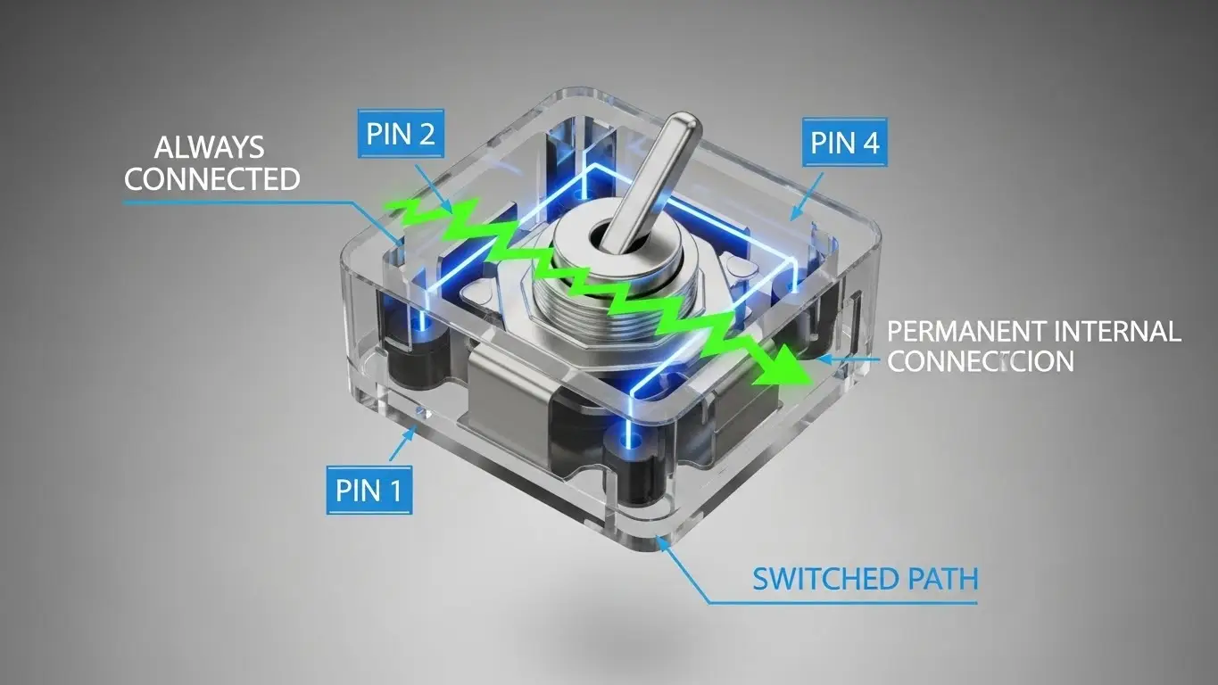
- The Internal Bridge: Internally, the pins are connected in pairs. Pin 1 is permanently connected to Pin 2; Pin 3 is permanently connected to Pin 4.
- The Switch Action: The actual switching happens between the pairs. When you press the button, the metal dome bridges the gap between the [1-2] pair and the [3-4] pair.
To avoid shorting your circuit or creating a "always on" connection, you should always connect your wires across the diagonal (e.g., Top-Left and Bottom-Right). For a deeper look at the internal mechanics and different sizes available, check our Introduction to Tact Switches.
Designing the Circuit: Logic Levels and Resistors
You cannot simply connect a switch between a pin and 5V. If you do, the pin is "floating" when the switch is open, acting like an antenna that picks up random noise. This causes your microcontroller to read random inputs.
The Pull-Up Resistor Configuration
To fix this, we use a "Pull-Up" or "Pull-Down" resistor configuration. In professional embedded design, Active Low (Pull-Up) is the standard.
- Connection: Connect the microcontroller pin to Ground through the switch.
- Resistor: Connect the same pin to Voltage (VCC) through a resistor (usually 10kΩ).
- Result: The pin reads HIGH (1) by default. When you press the button, it connects to Ground, reading LOW (0).
For a detailed explanation of why we prefer this "Active Low" method and how to calculate resistor values, read our guide on How Switches Control Logic Levels.
The Software Layer: Handling "Switch Bounce"
Once your hardware is wired, you might notice a problem: pressing the button once causes the microcontroller to register multiple clicks.
This is called Switch Bounce. When the metal contacts inside the switch collide, they vibrate microscopically for a few milliseconds. A fast microcontroller (running at millions of instructions per second) sees this vibration as: On-Off-On-Off-On.
How to Fix Bounce
- Software Debouncing: The easiest fix. In your code, when a press is detected, tell the processor to wait (delay) for 10-50 milliseconds before checking the pin again. This allows the physical vibration to settle.
- Hardware Debouncing: Adding a small capacitor (0.1µF) across the switch legs to smooth out the voltage spikes.
Polling vs. Interrupts: Two Ways to Listen
When writing your firmware, you have two ways to check the switch status.
1. Polling (The Beginner Method)
The microcontroller constantly checks the pin status inside the main loop().
- Pros: Simple to code.
- Cons: Wastes processor power; can miss a quick press if the processor is busy doing other tasks (like driving a display).
2. Interrupts (The Pro Method)
You configure a hardware interrupt pin. The microcontroller ignores the button until it is pressed. When the signal changes, the processor pauses whatever it is doing, runs the button code, and then resumes.
- Pros: Extremely efficient; never misses a press.
- Cons: More complex to debug.
Troubleshooting Common Issues
If your project isn't reacting to inputs, follow this checklist:
- Check the basics: Is the switch actually closing the circuit? Use a multimeter to verify. You can learn the step-by-step process in The Simplest Way to Test a Tact Switch.
- Check the mounting: If you are using a breadboard, tact switches can sometimes pop out or have poor contact. If you are designing a custom PCB, ensure you chose the right footprint (THT vs SMD). See What Beginners Should Know About PCB Switches for mounting tips.
- Verify the logic: Are you confusing a momentary tact switch with a latching switch? If your code expects a signal to stay "On" but the user releases the button, your logic might fail. Compare these behaviors in How DIP Switches Are Used in Basic Electronics.
Ruggedizing Your Interface
For a prototype on your desk, a standard tact switch is fine. But if you are building a controller for a CNC machine, a robot, or an outdoor weather station, you need to consider the environment.
Standard tact switches are not waterproof. Dust and moisture can get inside the dome, causing the "bounce" issue to worsen over time or the switch to fail entirely. For projects exposed to the elements, you must select sealed switches or industrial-grade components. You can explore high-durability options in our Industrial Switches Comprehensive Guide.
Frequently Asked Questions
INPUT_PULLUP? No. Most modern microcontrollers (like Arduino ATMega328 or ESP32) have internal resistors built into the chip. By using pinMode(pin, INPUT_PULLUP), you enable them, simplifying your wiring.
Directly? Generally, no. Tact switches are for logic signals (low current). They cannot handle the current required to power the whole board. You would need a MOSFET or a dedicated power management circuit.
For most standard tact switches, 20ms to 50ms is the "sweet spot." It is long enough to filter out noise but short enough that the user doesn't feel a lag.
This is the classic symptom of a "Floating Pin." You likely forgot the pull-up/pull-down resistor, or your ground connection is loose.
Key Takeaways
- Connect Diagonally: When using 4-pin tact switches, connect wires to opposite corners to ensure a valid circuit.
- Don't Float: Always define the voltage state using resistors (Internal
INPUT_PULLUPis easiest). - Debounce is Vital: A raw switch signal is noisy; filter it in code or hardware to prevent double-triggering.
- Choose the Right Method: Use "Polling" for simple loops and "Interrupts" for complex, power-sensitive projects.
Conclusion
Tactile switches are the most fundamental building block of user interaction in embedded systems. While connecting two wires seems trivial, the difference between a glitchy prototype and a professional device lies in how you handle the details: the floating pins, the signal bounce, and the component selection.
Now that you understand the logic, double-check your component choice. Ensure you aren't using a configuration switch when you need an input button—review the differences in How DIP Switches Are Used in Basic Electronics.