
Product Specification
Product Description
Application Field
Why Choose Us
Product Description
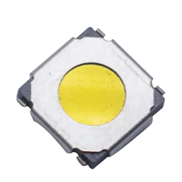
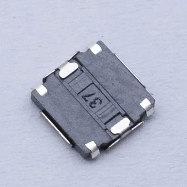
This ultra‑compact, top‑actuated tactile push button switch is designed for high‑density SMT assemblies. Its J‑bend (gullwing) terminals create robust solder joints and excellent board retention while keeping a low profile. Available in 4.0×4.0 mm and 5.2×5.2 mm body sizes, it delivers a crisp, consistent click with multiple actuation force and height options. Ideal for consumer, industrial, and IoT interfaces that require reliable momentary input and fast, clean tactile response.
Key Features
- Two compact footprints: 4×4 mm and 5.2×5.2 mm
- J‑bend SMT terminals for strong solder fillets and reworkability
- SPST‑NO, momentary action with sharp tactile feedback
- Multiple forces available: 160/200/250/320 gf (±20%)
- Short travel for quick, precise actuation (typ. 0.2–0.35 mm)
- Low profile with several actuator heights for stack‑up flexibility
- Long mechanical life up to 100k–300k cycles (option‑dependent)
- Stable contact performance, low bounce time
- Heat‑resistant housing suitable for reflow soldering
- Tape‑and‑reel packaging for automated placement
- RoHS and REACH compliant
Typical Applications
- Remote controls, set‑top boxes, handheld instruments
- Wearables, IoT nodes, smart home devices
- Keypads and control panels in appliances and tools
- Test/measurement and medical disposables (non‑critical)
- Automotive interior electronics (non‑safety)
Electrical and Mechanical Specifications
- Function: SPST‑NO, momentary
- Electrical rating (resistive): up to 50 mA @ 12 VDC (consult for higher/lower level ratings)
- Contact resistance: ≤100 mΩ initial
- Insulation resistance: ≥100 MΩ @ 100 VDC
- Dielectric strength: 250 VAC, 1 minute
- Bounce time: ≤10 ms
- Actuation force options: 160/200/250/320 gf (±20%)
- Total travel: 0.2–0.35 mm (typical)
- Operating life: 100,000–300,000 cycles (depends on force/plating)
- Operating temperature: −20 to +85 °C
- Storage temperature: −40 to +85 °C
Materials and Construction
- Housing/base: heat‑resistant thermoplastic, UL94 V‑0
- Plunger/actuator: POM or equivalent engineering resin
- Snap dome: stainless steel
- Contacts: silver alloy; gold over nickel available for low‑level signals
- Terminals: copper alloy, tin‑plated (J‑bend SMT)
Footprint and Dimensions
- Body sizes: 4.0 × 4.0 mm; 5.2 × 5.2 mm
- Actuator height options: low to medium profiles available (e.g., ~1.5–5.0 mm; option‑dependent)
- Actuator diameter: ~2.0–2.5 mm (variant‑dependent)
- Terminal style: 4‑terminal, corner J‑bend gullwing
Note: For exact land pattern, keep‑out, and height stack‑ups, request the mechanical drawing for the selected variant.
Soldering and Handling
- Reflow soldering (recommended): per JEDEC J‑STD‑020; peak 255–260 °C, time above 217 °C ≤60 s; up to 2 reflow cycles
- Hand solder: tip 350 °C max, ≤3 s per terminal; avoid mechanical stress
- Wave solder: not recommended for SMT J‑bend packages
- Cleaning: use no‑clean flux or controlled post‑reflow cleaning; prevent solvent ingress through actuator
- Do not press the actuator during pick‑and‑place or reflow; avoid over‑travel in assembly
Compliance and Quality
- RoHS and REACH compliant
- Halogen‑free options available
- Manufactured under ISO 9001 quality management
Packaging
- Tape‑and‑reel, 8 mm embossed tape with pick‑and‑place cover film
- Typical reel counts: 2,500–4,000 pcs/reel (varies by size/height)
- Bulk/tray packaging available for samples
Options and Ordering
- Body size: 4×4 mm or 5.2×5.2 mm
- Actuation force: 160/200/250/320 gf
- Actuator height: multiple low/standard/high options
- Contact plating: silver (standard) or gold over nickel (low‑level)
- Locating pegs/posts: optional
- Keycap compatibility: flat/concave caps in various colors
Example order code (illustrative): JTS‑52‑H25‑250GF‑Ag or JTS‑40‑H20‑160GF‑Au
Please consult the ordering guide for exact suffix definitions.
Accessories
- Snap‑on keycaps in multiple heights and colors
- Light pipes and bezels for panel alignment
- Dust covers/boots at panel level for improved contamination resistance
Design Tips
- Implement debounce (hardware RC or firmware) for 5–10 ms
- Use gold‑plated contacts for <10 mA or low‑voltage logic signals
- Provide an external over‑travel stop in the keycap/panel to protect the dome
- Balance pad sizes and use solder‑mask‑defined (SMD) pads to control solder wicking on J‑bend leads
- Minimize side‑loads from the key mechanism; ensure perpendicular actuation
Notes
- Specifications are typical and may vary with selected options. For guaranteed limits, recommended land pattern, 3D CAD, and reliability data, request the latest datasheet for the exact 4×4 or 5.2×5.2 J‑bend SMT variant.