Installation & Usage Made Simple
In the world of industrial automation, a switch is only as reliable as its installation. It is a frustration we hear often: a high-quality pressure or flow switch fails prematurely, not because of a manufacturing defect, but due to a subtle oversight during the setup phase.
At hx-switch.eu, we understand that precision is non-negotiable. Whether you are managing a hydraulic power unit or a complex HVAC system, the longevity of your instrumentation depends on how it is handled before the system is ever pressurized.
This guide strips away the complex academic jargon to provide a definitive, field-tested protocol for installing, wiring, and adjusting your industrial switches. We are looking beyond the basic manual to cover the real-world nuances that prevent downtime and ensure safety.
Pre-Installation Checklist: Safety & Compatibility
Before a wrench ever touches a fitting, a few critical checks can save thousands of dollars in damaged equipment. A significant portion of switch "failures" are actually specification mismatches that occur before installation begins. If you are still in the selection phase, it is vital to understand how to choose the right switch for your specific media and environment.
The Compatibility Check
The first step is verifying wetted parts compatibility. Does the switch material match the media?
- Brass: Generally suitable for water, air, and neutral oils.
- Stainless Steel (316L): Required for aggressive chemicals or high-purity applications.
- Seals (Viton/NBR/EPDM): Ensure the seal material won't swell or degrade when in contact with your specific fluid.
Electrical Load Assessment
This is the most common silent killer of switches. You must distinguish between Resistive and Inductive loads.
- Resistive Loads: Simple heaters or lights. The current is constant.
- Inductive Loads: Solenoids, motors, and relays. These create a "kickback" voltage (arc) when the switch opens, which can burn contacts instantly if not suppressed. If you are switching a heavy solenoid, verify if your switch requires an arc suppression relay.
The Environmental Scan
Check the IP Rating (Ingress Protection) against the installation zone. A standard IP65 switch can handle low-pressure water jets, but if you install it in a washdown zone requiring IP67 or IP68, moisture will eventually wick into the housing, corroding the contacts.
Physical Mounting and Process Connection
The physical connection connects the sensor to your process. The goal here is to transmit pressure accurately while protecting the device from physical trauma.
Orientation Matters
While many modern electronic switches can be mounted in any position, mechanical diaphragm switches perform best when mounted vertically, with the connection pointing down. This prevents sediment, sludge, or metal shavings from settling directly onto the diaphragm, which can harden over time and affect the switch point accuracy.
Thread Sealing Best Practices
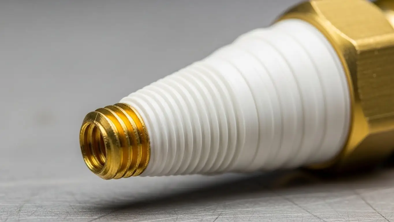
This is a topic of constant debate: Liquid Sealant vs. PTFE (Teflon) Tape.
Our engineering team generally recommends PTFE tape for standard tapered threads, but with a strict warning: Application technique is critical.
The Golden Rule of Sealing:
- Clean the threads thoroughly.
- Start wrapping the tape one thread back from the end.
- Leave the first thread bare.
If tape hangs over the edge of the fitting, shreds can be sheared off during tightening. These shreds travel into the system and can lodge in the switch's orifice or pilot valves, causing immediate system failure.
Dampening and Protection
If your application involves steam or high-temperature fluids (above 80°C), the switch should not be mounted directly to the pipe. Use a syphon (pigtail) or a capillary line. This simple addition dissipates heat, ensuring the fluid touching the switch diaphragm is within a safe temperature range.
Electrical Wiring & Logic (N.O. vs. N.C.)
Once the switch is mechanically secure, the next step is integrating it into your control logic. Confusion here often leads to systems that behave inversely to what the operator expects.
Understanding the Logic
- Normally Open (N.O.): The circuit is disconnected (OFF) in its resting state. It closes (turns ON) when the pressure rises to the setpoint.
- Normally Closed (N.C.): The circuit is connected (ON) in its resting state. It opens (turns OFF) when the pressure rises to the setpoint.
- SPDT (Single Pole Double Throw): The industry standard. It offers three terminals (Common, N.O., and N.C.), allowing you to choose the logic or use one switch to control two different actions (e.g., turn off a pump and trigger an alarm).
Wiring Protocol for Reliability
- Use Ferrules: Never insert stranded wire directly into the terminal block. Over time, vibration causes strands to spread and loosen, creating "hot spots" or intermittent signals. Always crimp a ferrule onto the wire end.
- Torque Correctly: Overtightening terminal screws can crack the PCB or housing. Tighten until snug, then give a quarter turn.
- Seal the Gland: The cable gland is the primary entry point for moisture. Ensure the outer sheath of the cable passes through the rubber seal of the gland. Tightening the gland onto the individual wires creates gaps where water will enter.
Calibration: Setting the Switch Point & Hysteresis
Adjusting a pressure switch is not just about picking a number; it is about balancing system stability.
Key Definitions
- Setpoint (Cut-out/Cut-in): The pressure at which the switch activates.
- Reset Point: The pressure at which the switch returns to its original state.
- Hysteresis (Deadband): The difference between the Setpoint and the Reset Point.
The Adjustment Process
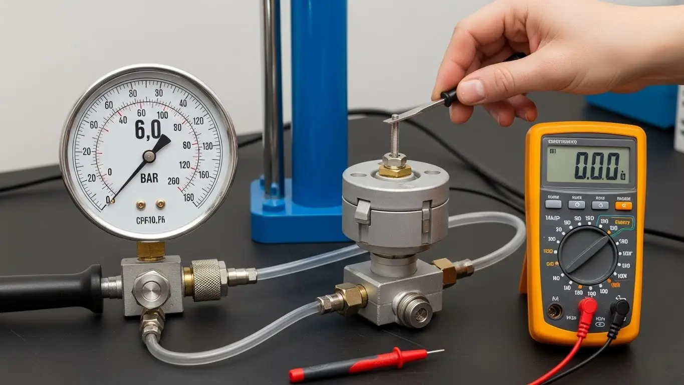
To calibrate accurately, you cannot rely on the process pressure alone. You need a controlled environment: a test pump, a reference pressure gauge, and a multimeter (set to continuity/beep mode).
- Connect the multimeter across the Common and N.O. terminals.
- Pressurize the system slowly until you reach your desired switching pressure.
- Adjust the Setpoint Screw: If the multimeter hasn't beeped, turn the adjustment screw (usually clockwise to increase tension) until the switch clicks and the meter beeps.
- Check Hysteresis: Slowly lower the pressure. Note the pressure reading when the meter stops beeping. This gap is your hysteresis.
Note: On many mechanical switches, hysteresis is fixed (usually 10-20% of the range). If you need a specific reset point different from the fixed percentage, you may need an adjustable differential switch or an electronic pressure switch.
Common Usage Mistakes & Troubleshooting
Even with the best components, issues can arise. Here is what we see most often in the field and how to solve it.
The "Chattering" Switch
If your switch is turning on and off rapidly (machine gun sound), your system likely has pressure pulsations or the hysteresis is too tight.
- Solution: Install a snubber (dampener) on the process connection to smooth out pressure spikes, or switch to a unit with a wider deadband.
Setpoint Drift
"The switch tripped at 10 bar last month, now it trips at 9.5."
- Cause: Mechanical fatigue is normal in high-cycle applications.
- Solution: All mechanical springs relax slightly over time. We recommend a calibration check every 6–12 months depending on cycle frequency. If high accuracy is required permanently, an electronic switch is the superior choice.
Leakage at the Port
If you see fluid leaking from the electrical housing, the diaphragm or piston seal has failed.
- Cause: This is usually due to chemical incompatibility or pressure spikes exceeding the "Proof Pressure" (burst pressure) of the unit.
- Solution: Replace the unit immediately. Do not attempt to repair a ruptured diaphragm switch; the structural integrity is compromised.
Conclusion
Correct installation is the bridge between a high-quality component and a high-reliability system. By paying attention to thread sealing, proper wiring termination, and precise calibration, you ensure your equipment operates safely and efficiently for years.
The majority of "switch failures" are solved in the first hour of installation. Take the time to do it right.
The Bottom Line:
- Verify chemical and electrical compatibility before starting.
- Use ferrules and proper cable gland sealing.
- Set your hysteresis to prevent rapid cycling.
If you are unsure which switch specification fits your unique application, or if you need custom adjustment advice, our engineering team at hx-switch.eu is ready to assist.
Frequently Asked Questions
N.O. (Normally Open) means the circuit is disconnected until the pressure setpoint is reached. N.C. (Normally Closed) means the circuit is connected until pressure rises to the setpoint, at which point it breaks the connection. N.O. is common for "turn on" functions; N.C. is common for safety/cutoff functions.
Chattering happens when pressure fluctuates rapidly around the setpoint. You can fix this by increasing the hysteresis (deadband) setting or installing a snubber (dampener) at the inlet to smooth out pressure spikes from the fluid.
No. Standard switches can generate a small spark (arc) when contacts open. For hazardous zones (Zone 0, 1, or 2), you must use an ATEX or IECEx certified explosion-proof switch designed to contain any internal explosion or limit energy to prevent ignition.
We recommend checking mechanical switches every 6 to 12 months. Springs can experience "relaxation" or fatigue over thousands of cycles, causing a slight drift in the setpoint. Critical safety switches should be tested more frequently.
The deadband (hysteresis) is the mechanical differential required to reset the switch. It prevents the switch from oscillating wildly if the pressure hovers exactly at the setpoint. It is created by the physical properties of the spring and micro-switch travel distance.