How to Wire a DIP Switch in a Circuit
To wire a DIP switch correctly, you generally connect one side of the switch pins to the ground (GND) and the corresponding pins on the other side to the digital input pins of your microcontroller or logic circuit. Crucially, you must ensure the signal state is stable by using a pull-up resistor. You can either add an external 10kΩ resistor connecting the input pin to the voltage source (VCC) or enable the microcontroller’s internal pull-up feature via software. This configuration ensures the circuit reads a logic "1" (High) when the switch is open and a logic "0" (Low) when the switch is closed (ON), preventing the "floating" signals that cause erratic errors.
What Is the Standard Wiring Configuration?
The most reliable way to wire a DIP switch is using the "active low" configuration with a pull-up resistor. In this setup, the default state of the input pin is HIGH (logic 1) because the resistor pulls it up to VCC. When you flip the switch to "ON," it connects the pin directly to Ground, forcing the signal LOW (logic 0).
Why Avoid Floating Inputs?
If you wire a switch without a resistor—just connecting a pin to VCC when ON and nothing when OFF—the "OFF" state is not effectively zero volts; it is an open circuit. This acts like an antenna, picking up static electricity and radio interference.
For robust industrial applications, understanding how to secure these connections physically is just as important as the electrical theory. You can learn more about ruggedizing your setup in our Industrial Switch Installation Guide.
Do I Need External Resistors for Every Switch?
Not always. Most modern microcontrollers (like Arduino, ESP32, or STM32) have built-in internal pull-up resistors that you can enable via code. This simplifies the wiring significantly, as you only need to connect the switch between the GPIO pin and Ground.
However, if you are working with discrete logic gates (like 7400 series chips) or older hardware, external resistors are mandatory. If you neglect this, you will encounter random signal changes. We detail how to diagnose these specific ghost signals in our guide on DIP switch reading errors and troubleshooting.
Table: Internal vs. External Pull-Up Comparison
| Feature | Internal Pull-Up | External Pull-Up |
| Component Count | Low (Switch only) | High (Switch + Resistor Array) |
| Noise Immunity | Moderate (Weak resistance ~30kΩ) | High (Can verify resistance, e.g., 4.7kΩ) |
| PCB Space | Minimal | Requires extra footprint |
| Use Case | Consumer Electronics, Prototyping | Industrial, High-Noise Environments |
How Do You Connect a DIP Switch to a Breadboard?
Standard DIP switches have a 2.54mm (0.1 inch) pin pitch, making them perfectly compatible with standard breadboards. To wire it, place the switch so that it straddles the center trench of the breadboard. This isolates the two rows of pins from each other.
Layout Considerations
Connect the top row of pins to your input wires and the bottom row to the ground rail (or vice versa). When designing a custom circuit board later, ensuring the holes match this spacing is critical. You can read about the specifics of pad spacing in our article on Tact switch PCB footprint design, as the principles for pitch and land patterns are very similar for DIP packages.
How Do You Solder DIP Switches to a PCB?
Insert the switch legs through the PCB holes, apply a small amount of flux, and heat the pad and lead simultaneously with a soldering iron set to roughly 350°C. Feed a small amount of solder to form a concave "volcano" shape.
Managing Heat Sensitivity
Even though DIP switches look rugged, the plastic housing can melt if you hold the iron there too long, which can lock the internal sliding mechanism.
- Step 1: Secure the switch with tape so it is flush against the board.
- Step 2: Solder one corner pin first to anchor it.
- Step 3: Check alignment before soldering the rest.
This process shares many similarities with how to solder SMD tact switches, where heat management is the number one priority to prevent component damage.
Can I Use SMD DIP Switches Instead of Through-Hole?
Yes, Surface Mount (SMD) DIP switches are available and work electrically the same way, but they require different assembly techniques. Instead of legs going through the board, they have "gull-wing" or "J-lead" feet that sit on surface pads.
Assembly Differences
For SMD versions, you will typically use solder paste and a reflow process, or careful hand soldering with a fine tip. The logic of wiring—Pin to Ground, Pull-up to VCC—remains identical. If you are moving toward surface mount technology for your project, reviewing how to assemble a tact switch on SMD board will give you the right mindset for handling these smaller, heat-sensitive components.
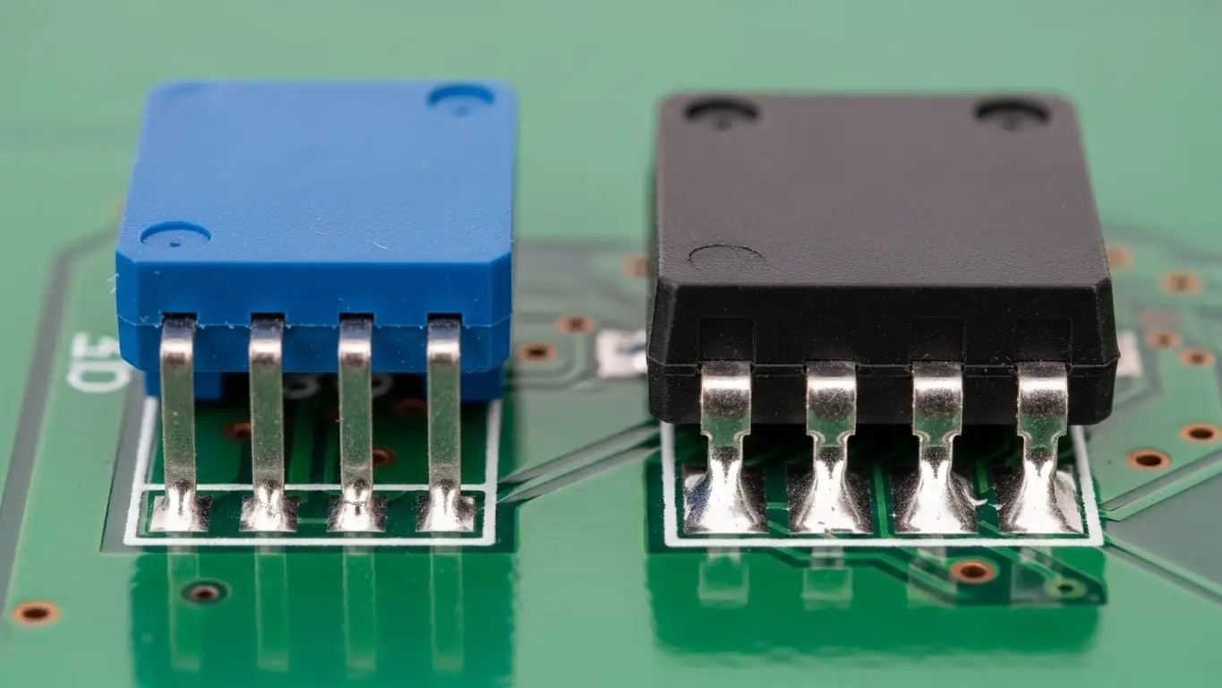
[Image Suggestion: Close-up photo of an SMD DIP switch soldered onto a green PCB compared to a through-hole version. Alt Text: Comparison of Surface Mount vs. Through-Hole DIP switch mounting.]
How Do I Verify the Wiring Logic?
Once wired, you must verify that the logic levels correspond to your expected binary code. Typically, if using pull-ups, "ON" equals 0 and "OFF" equals 1. This inversion often confuses beginners.
If you are setting an address or a mode, you need to translate the physical switch positions into the data your software expects. For a deep dive into decoding these positions, check our guide on how to read DIP switch settings.
Frequently Asked Questions
Without a resistor (floating state), the input pin will randomly flip between HIGH and LOW due to electrical noise. Your device will behave erratically or fail to register the settings.
Generally, no. DIP switches are designed for low-current signal logic (typically 25mA to 100mA). Powering a motor directly through them will likely melt the internal contacts. Use the switch to control a transistor or relay instead.
A resistor network is a single component that contains multiple resistors (usually 8) in one package. It is commonly paired with DIP switches to provide pull-up resistors for all 8 switches simultaneously, saving PCB space.
DIP switches are non-polarized mechanical switches. It does not matter which side connects to Ground and which connects to the Pin, as long as the circuit loop is consistent.
Standard DIP switches are not waterproof. You can buy specific sealed models (usually with a tape seal on top) for soldering, but for operation, you should place the entire circuit inside a waterproof enclosure.
Key Takeaways
- Always Use Pull-Ups: Prevents floating signals. Use internal microcontroller pull-ups to save space.
- Logic is Inverted: With pull-ups, the switch "ON" usually sends a Logic "0" (Low) signal.
- Heat Control: When soldering, work quickly to avoid melting the plastic housing.
- Check Ratings: Only use DIP switches for signal/logic currents, not high-power loads.
Conclusion
Wiring a DIP switch is a fundamental skill that relies on one core concept: never leave an input pin floating. Whether you are using a breadboard for a prototype or designing a permanent industrial PCB, connecting the switch to Ground and using a pull-up resistor ensures reliable data entry. Once wired, always verify your logic levels with a multimeter to ensure your "ON" really means "ON."