How to Test DIP Switches with a Multimeter
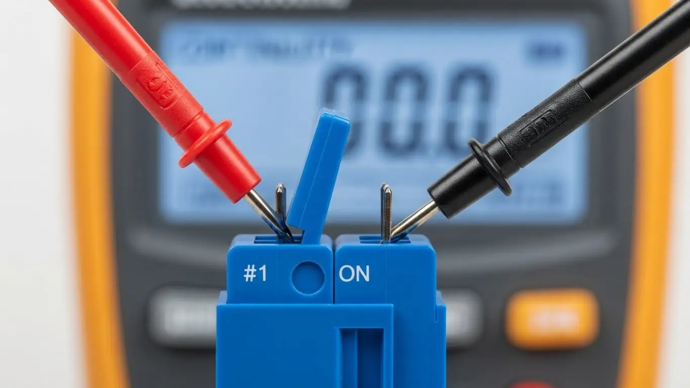
To test a DIP switch with a multimeter, set your meter to Continuity Mode (indicated by a sound wave or diode symbol). Place your black and red probes on the two parallel pins corresponding to a single switch position (across the body width, not side-by-side). When you toggle the switch to ON, the multimeter should beep and display close to 0Ω. When toggled to OFF, the meter should stop beeping and display OL (Open Loop) or infinity.
If testing in-circuit (on a PCB), be aware that parallel resistors may cause false positive beeps; in these cases, switching to Resistance Mode is required for an accurate diagnosis.
Understanding the DIP Layout Before You Test
Before touching probes to metal, you must understand the pinout. A standard DIP (Dual In-line Package) switch is essentially a row of independent SPST (Single Pole Single Throw) switches packed together.
- The "Gang" Layout: A 4-position DIP switch has 8 pins total.
- The Connection: The switch connects the pin on the top row to the pin directly across from it on the bottom row.
- No Internal Common: Unlike some rotary switches, standard slide DIP switches do not share a common ground or power rail internally. Each vertical pair is electrically isolated.
If you are installing a new component rather than testing an old one, refer to a proper industrial switch installation guide to ensure you don't damage the pins during insertion.
Method 1: The Continuity Test (Quick Check)
This is the fastest way to verify if a switch is making contact.
- Isolate the Component: If possible, remove the switch from the circuit. If it is soldered in, ensure the device is fully powered down and capacitors are discharged.
- Set Multimeter: Turn the dial to Continuity Mode (look for the sound wave symbol).
- Touch Probes: Touch the two probes together to verify the beep.
- Test the Switch:
- Place one probe on Pin 1 (Top) and the other on Pin 1 (Bottom).
- Flip the switch actuator to ON.
- Result: You should hear a continuous beep.
- Flip the actuator to OFF.
- Result: The beep should stop immediately.
- Repeat: Move down the line to switch positions 2, 3, 4, etc.
Method 2: The Resistance Test (Precision Check)
The continuity beep only tells you if the circuit is closed; it doesn't tell you how well it is closed. Old DIP switches often suffer from oxidation, creating high resistance that causes data errors.
- Set Multimeter: Turn the dial to the lowest Ohms (Ω) setting (usually 200Ω).
- Connect Probes: Connect across the top and bottom pins of the switch.
- Measure ON State:
- Flip the switch to ON.
- Good Reading: 0.1Ω to 0.5Ω.
- Bad Reading: > 1.0Ω. (This indicates oxidation or weak contact).
- Measure OFF State:
- Flip the switch to OFF.
- Good Reading: "OL" (Open Loop) or > 1MΩ.
- Bad Reading: Any low number (indicates a short circuit or solder bridge).
Pro Tip: While holding the probes, gently wiggle the switch actuator while it is in the ON position. If the numbers on your multimeter jump wildly (e.g., from 0.5Ω to 20Ω), the internal contacts are dirty or worn out.
Troubleshooting: Why Do I Get "Beeps" When the Switch is OFF?
This is the most common confusion when testing In-Circuit (when the switch is soldered to the PCB).
DIP switches are often wired in parallel with pull-up or pull-down resistors. Even when the DIP switch is open (OFF), your multimeter might measure the resistance of the resistor (e.g., 1kΩ or 10kΩ).
- The False Positive: Some multimeters will beep for anything under 50Ω or 100Ω. If you are checking a low-impedance circuit, you might get a beep even if the switch is open.
- The Solution: Always use Resistance Mode for in-circuit testing. If the switch is OFF but you read 10kΩ, that is likely the pull-up resistor. If you toggle it ON and it drops to 0Ω, the switch is working correctly.
For more details on how these components integrate into board layouts, see our guide on how to install a tact switch on PCB, which covers similar soldering and circuit principles.
Can I Repair a Faulty DIP Switch?
If you detect high resistance (e.g., 50Ω when ON), the contacts are likely oxidized. Before desoldering, try this:
- Apply Cleaner: Use a specialized electronic contact cleaner (like DeoxIT). Spray a tiny amount into the switch mechanism.
- Cycle the Switch: Rapidly toggle the switch ON and OFF 10-20 times. This mechanical friction helps scrub the oxidation off the internal contacts.
- Retest: Perform the Resistance Test again.
If resistance remains high, the unit must be replaced. Ensure you verify the new settings before installation—learn more about this in our article on how to configure DIP switch positions.
Frequently Asked Questions
Not accurately. You can build a simple "test rig" using a battery and an LED. If the LED lights up when the switch is ON, current is flowing. However, this won't detect high resistance (corrosion) that might confuse sensitive digital logic circuits.
Always connect to the pins directly opposite each other. Pin 1 (top) connects to Pin 1 (bottom). Adjacent pins (Pin 1 and Pin 2 on the same side) are not connected unless you have bridged them on the PCB.
A healthy, new DIP switch should have a contact resistance of less than 100 milliohms (0.1Ω). Any reading above 1-2 Ohms suggests the switch is degrading and may cause signal issues.
This is usually caused by internal dust or oxidation. The "wiggle test" described above can confirm this. In industrial environments, vibration can also cause the internal spring mechanism to weaken over time.
Key Takeaways
- Check Continuity First: Use the "beep" mode for a quick pass/fail check on loose switches.
- Use Resistance for Accuracy: Checking Ohms (Ω) helps identify dirty contacts that "beep" but fail to pass clean data signals.
- Beware In-Circuit Readings: Other components on the board (resistors) can mimic a closed switch. Always verify the schematic if testing without desoldering.
- Cycle to Clean: Often, toggling an old switch back and forth rapidly can clear oxidation and restore functionality.
Conclusion
Testing a DIP switch is a fundamental skill for troubleshooting legacy electronics and configuring new industrial boards. By using a multimeter to verify both continuity and resistance, you ensure that your hardware settings are being read correctly by the microcontroller. If a switch fails the resistance test even after cleaning, replace it immediately to prevent data corruption.