How to Solder SMD Tact Switches: Hand & Hot Air Guide
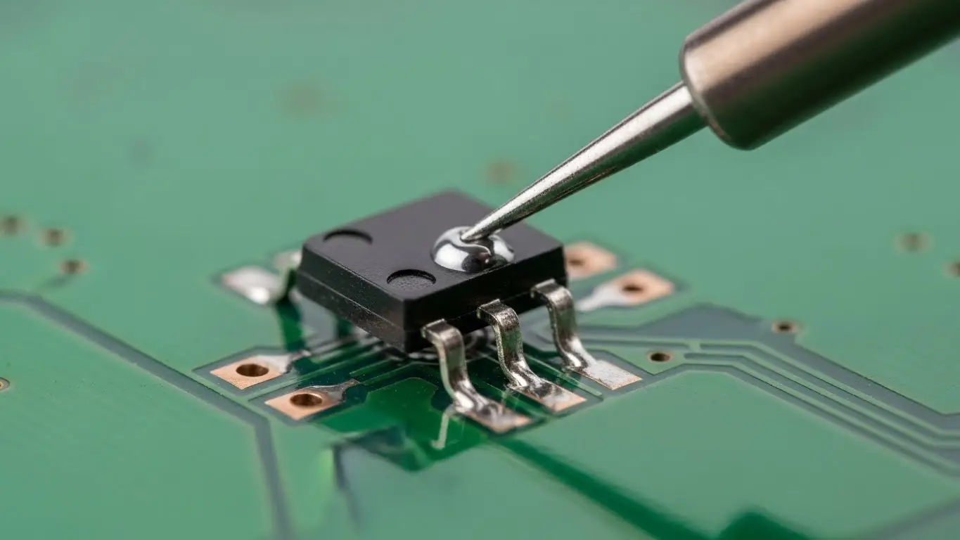
To solder an SMD tact switch effectively, use the "Tack and Reflow" method. First, apply a small amount of solder to one PCB pad only. Holding the switch with tweezers, heat that tinned pad and slide the component into place until it sits flush. Remove the heat and let it set to anchor the switch. Finally, solder the remaining legs.
Unlike passive components (resistors/capacitors), tact switches contain moving plastic parts and delicate internal metal domes. Excessive heat (>350°C) or liquid flux can ruin the clicking mechanism instantly. This guide covers the precise techniques to solder them without destroying their tactile feel.
Prerequisites: Tools & Temperature
Before you begin, ensure your environment is ready. If you are setting up a production line or a robust prototype, reviewing a comprehensive industrial switch installation guide is recommended to understand the broader context of component longevity.
Essential Tools:
- Soldering Iron: Set to roughly 330°C - 350°C. Going hotter increases the risk of melting the plastic housing.
- Fine Tip: A chisel or conical tip works best for reaching gull-wing leads.
- Flux: Gel Flux is preferred over liquid flux. Liquid flux flows too easily and can wick inside the switch mechanism, causing contact failure.
- Tweezers: Fine-point, angled tweezers are ideal for alignment.
Method 1: The Hand Soldering Technique (Safest)
This method gives you the most control over heat input, minimizing the risk of melting the button.
Step 1: Pad Preparation
Clean the PCB pads with isopropyl alcohol. Apply a tiny amount of solder to only one of the four pads. Leave the others bare.
Step 2: The "Tack"
Grab the switch with your tweezers. Heat the tinned pad with your iron. While the solder is molten, slide the switch leg into the puddle.
- Critical Check: Ensure the switch body is flat against the PCB surface. If it floats, the mechanical stress of pressing the button will eventually rip the pads off.
Step 3: Alignment & Anchor
Remove the iron but keep holding the switch steady with tweezers until the solder solidifies (about 2 seconds). Now, let go.
- Tip: Gently nudge the switch. If it moves, re-melt and adjust. This alignment is vital for complex boards—see our guide on how to install a tact switch on PCB for more on component placement.
Step 4: Solder Remaining Legs
Now that the switch is anchored, apply a small dab of gel flux to the remaining three legs. Touch the iron tip to the pad and lead simultaneously, feeding in a tiny amount of solder wire. The joint should look like a shiny, concave "skirt."
Method 2: Hot Air Reflow (Fastest for Batches)
Hot air is efficient but risky. The plastic housing of a tact switch can melt if the airflow is too hot or directed for too long.
- Paste Application: Apply solder paste to all four pads. Use a stencil for precision if available.
- Placement: Drop the switch onto the paste. The surface tension will help it self-align.
- Reflow: Set your hot air station to 280°C - 300°C with low airflow.
- Technique: Move the nozzle in circles around the legs of the switch. Do not aim directly at the center button.
- Visual Cue: Watch for the paste to turn from gray paste to shiny silver liquid.
- Cool Down: Stop heating immediately once the solder flows. Do not touch the switch until it is cool, or you might displace it.
The "Flux Ingress" Danger Zone
A common failure in DIY electronics is a switch that "clicks" but doesn't work electrically. This is often caused by Flux Ingress.
- The Cause: Using too much liquid flux or washing the board with solvent after soldering. The fluid wicks inside the switch and coats the internal metal dome, insulating it.
- The Fix: Use gel flux sparingly. Never wash standard tact switches with solvent unless they are rated IP67 (sealed).
Verification & Testing
Once soldered, you cannot rely on visual inspection alone.
- Mechanical Check: Press the button. Does it have a crisp "snap"? If it feels mushy, you likely overheated the housing.
- Electrical Check: Use a multimeter in continuity mode.
- For a deeper dive on this, read our tutorial on how to test a DIP switch with a multimeter. The continuity principles are identical for tact switches.
- Configuration: If your switch is part of a larger input array, ensure your logic settings are correct. (See: How to configure DIP switch positions).
Frequently Asked Questions
A standard hardware store heat gun is too imprecise and usually too hot. It will likely melt the plastic housing. Use a proper hot air rework station with temperature control.
These refer to the shape of the metal legs. "Gull Wing" legs stick out away from the body (easier to hand solder). "J-Leads" curl underneath the body (saves space, but harder to hand solder).
You likely applied too much heat, causing the internal plastic plunger to deform and fuse with the housing. You will need to desolder and replace the unit.
For SMD parts, yes. The small amount of flux in the wire core is often insufficient for the flat pads of SMD footprints. External flux helps the solder flow quickly, reducing the time you need to apply heat.
Key Takeaways
- Tack First: Anchor one leg and align the component before soldering the rest.
- Watch the Heat: Keep iron temps under 350°C and limit contact time to <3 seconds to save the plastic housing.
- Avoid Liquid Flux: Excess liquid can wick inside and ruin the contact; use gel flux instead.
- Check Flushness: Ensure the switch body sits flat on the PCB to withstand pressing force.
Conclusion
Soldering SMD tact switches requires a balance of speed and precision. By prioritizing the "Tack and Reflow" method and being mindful of heat limits, you can install robust, reliable switches that maintain their crisp tactile feel. Always verify your work with a multimeter to ensure no flux has compromised the connection.