How to Read DIP Switch Settings
How to read dip switch settings is a fundamental skill for industrial technicians, retro-computing enthusiasts, and PCB designers. These compact components act as the hardware "voice" of a device, dictating behavior without a single line of software code. Whether you are configuring a DMX lighting controller or a garage door remote, understanding these binary codes is essential.
In my 15 years of experience handling electromechanical components, I’ve found that 90% of "hardware failures" are actually just misread switch positions. Let’s decode the logic behind these tiny levers and ensure your equipment is configured correctly.
What Are DIP Switch Settings and Why Do They Matter?
DIP switch settings are physical configurations of manual electric switches packaged in a Dual Inline Package (DIP) that represent binary data. They tell a device how to operate—such as setting a specific communication address, enabling a "test mode," or selecting a frequency band—by creating either an open (OFF) or closed (ON) circuit.
The Logic Behind the Levers
In an era of touchscreens, physical switches might seem archaic, but they offer unmatched reliability. A DIP switch bank is essentially a series of primitive logic gates. When you need to set a permanent configuration that shouldn't be wiped by a power outage or a software glitch, you use a DIP switch.
Understanding the "why" helps with the "how." When you look at a bank of 8 switches, you aren't just looking at plastic nubs; you are looking at a byte of data. Each switch represents a bit. If you are working in an industrial environment, correctly interpreting these settings is often the difference between a machine that runs smoothly and one that stays silent. For a broader look at setting up these components in complex environments, you can refer to our Industrial Switch Installation Guide.
How Do You Distinguish Between ON and OFF Positions?
To read the settings, locate the text printed on the switch housing, typically labeled "ON," "OPEN," or numbered. Pushing the actuator toward the "ON" text or the numbers usually creates a closed circuit (logic 1), while moving it to the opposite side creates an open circuit (logic 0).
Visual Cues and Manufacturer Variations
Not all manufacturers speak the same design language. While "Up is ON" is a common standard, it is not a universal law. I once spent two hours troubleshooting a legacy control board only to realize the manufacturer had inverted the labeling—"Open" was actually "Off" in their terminology.
Here is a checklist to ensure accuracy:
- Look for Labels: Most high-quality switches have "ON" printed clearly in white.
- Check the Arrow: Some surface mount switches use an arrow indicating the active direction.
- Feel the Click: A proper setting should have a tactile "snap." If the switch is floating in the middle, the connection is indeterminate.
If you are dealing with a particularly worn or dirty component where labels are obscured, you might need to verify the electrical state physically. This is where knowing how to test a DIP switch with a multimeter becomes a critical skill to ensure the physical position matches the electrical reality.
How Does Binary Code Relate to DIP Switches?
Each switch in a bank corresponds to a specific binary value, typically doubling as you move across the bank (1, 2, 4, 8, 16, 32, etc.). To read the total setting, you identify which switches are in the "ON" position and sum their corresponding values to determine the final address or numeric code.
The Math of Configuration
This is where people often get intimidated, but it is simple addition. Standard DIP switches are usually arranged in a row, labeled 1 through 8 (or more).
Example Calculation: Imagine a standard 8-position switch used for addressing:
- Switch 1 (Value 1): OFF
- Switch 2 (Value 2): ON
- Switch 3 (Value 4): OFF
- Switch 4 (Value 8): ON
- Switch 5-8: OFF
Calculation: 2 + 8 = Address 10.
If you are tasked with setting up a specific configuration, you work backward from the number you need. This binary approach is standard in networking equipment and older arcade hardware. For a step-by-step walkthrough on setting these values physically, read our guide on how to configure DIP switch positions.
How Do You Read Rotary vs. Slide DIP Switches?
Slide and rocker switches are read by the linear position of the actuator, whereas rotary DIP switches are read by the direction of an arrow dial. A rotary switch points to a hexadecimal (0-9, A-F) or decimal (0-9) character printed on the housing, representing a specific value without needing binary summation.
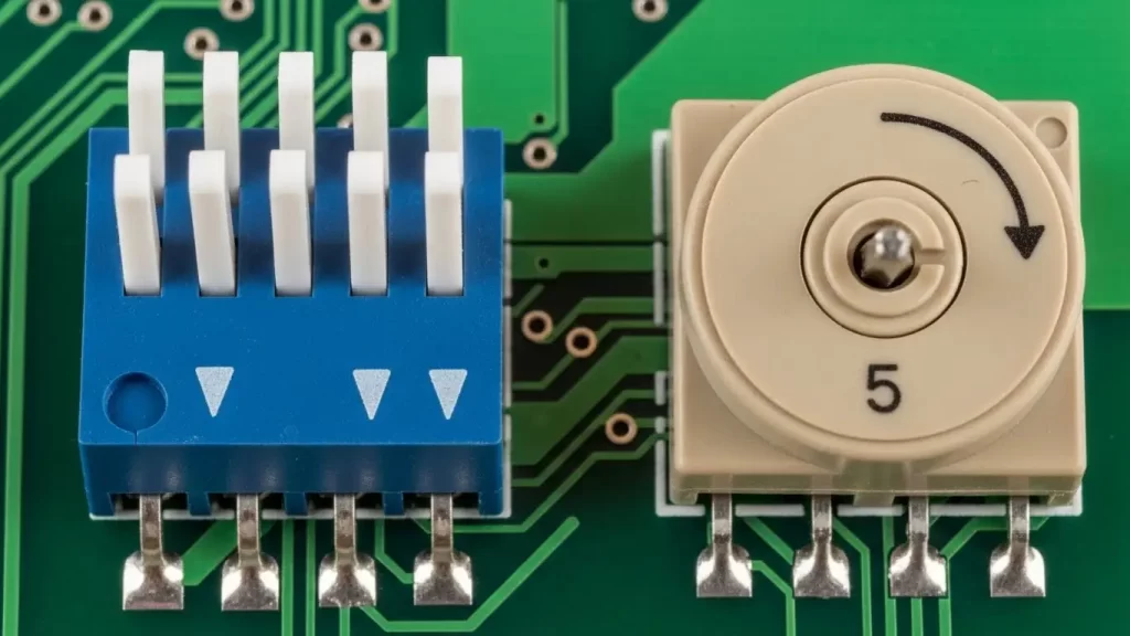
Identifying the Switch Architecture
- Slide/Rocker/Piano: These are the most common. You read them as a row of individual bits (10110010).
- Rotary: These look like small screws. You turn the center dial until the notch aligns with a number.
Rotary switches are frequently used in applications where space is tight, and the user needs to select one of 10 or 16 preset modes quickly. From a design perspective, the footprint differs significantly. If you are designing a board and need to decide between these types, reviewing the Tact switch PCB footprint design principles can help you understand spacing and layout requirements for different switch styles.
What Tools Are Required to Change Settings Safely?
Use a dedicated non-conductive adjustment tool, a plastic stylus, or a small flathead screwdriver designed for electronics. Avoid using graphite pencils, as the graphite dust is conductive and can cause short circuits across the switch contacts, leading to erratic device behavior.
protecting the Component
I have seen technicians use ballpoint pens to flip switches. The ink can gum up the actuator, and the metal tip can slip and scratch the PCB traces.
- Magnification: A magnifying glass or loupe is helpful for reading the tiny "ON" labels.
- Lighting: Good task lighting is essential to distinguish shadows from actual switch positions.
- Soldering Gear (If replacing): Sometimes, a switch is broken and cannot be read or set. In this case, you must replace it. While DIP switches are usually through-hole, similar principles apply if you are working with surface mount components. You can learn more about precision heating in our guide on how to solder SMD tact switches.
How Do You Troubleshoot Unresponsive Settings?
If a device does not recognize a new DIP switch setting, the most common fix is to power cycle the unit. Most microcontrollers only read the state of the DIP switches during the initial boot-up sequence; changing them while the device is powered on usually results in no change until the next restart.
Verification Checklist
- Power Cycle: Turn the device fully off, wait 10 seconds, and turn it back on.
- Continuity Check: Use a multimeter to ensure the switch isn't internally corroded.
- Seating: Ensure the switch is fully seated on the PCB.
- Soldering: Check for cold solder joints.
Sometimes, the issue isn't the switch, but how it was installed or interfaced with the board. If you are building a custom panel or troubleshooting a new build, ensure you followed the correct mounting procedures. See our tutorial on how to install tact switch on PCB for insights on proper component seating that apply to DIP switches as well.
Summary Data Table: Common DIP Switch Types
| Switch Type | Actuation Method | Readability | Typical Use Case |
| Slide DIP | Sliding a nub | High (Visual) | Address setting, Mode selection |
| Rocker DIP | Pressing a rocker | Medium | Industrial controls |
| Piano DIP | Side-actuated lever | High (Side view) | Edge-of-board access |
| Rotary DIP | Turning a dial | High (Direct value) | Frequency selection, IDs |
By mastering how to read DIP switch settings, you take control of your hardware. Always verify with a multimeter if in doubt, and remember: binary is just math, not magic.
Frequently Asked Questions (FAQ)
No, not always. While many manufacturers use "Up" for "ON," it depends on the brand and orientation of the switch installation. Always look for the "ON" label or numbering on the switch housing, or verify with a multimeter.
It is generally not recommended. Most devices only read the DIP switch positions during the startup (boot) sequence. Changing them while powered on usually has no effect until you restart the device.
You use binary calculation. Assign values to the switches (1, 2, 4, 8, 16, 32, 64, 128). Add the values of only the switches that are in the "ON" position. For example, if switches 1 and 3 are ON, the value is 1 + 4 = 5.
If you cannot see "ON" or "OFF," use a multimeter set to continuity mode. Place probes on the pins corresponding to a switch. If it beeps (low resistance), the switch is closed (ON). If it is silent, it is open (OFF).
A Slide DIP switch uses multiple levers to create a binary code (0s and 1s). A Rotary DIP switch uses a single dial that points to a specific number or letter (0-9 or A-F), making it easier to set a value without doing binary math.