How to Identify Tact Switch Pinout
To identify a standard 4-pin tact switch pinout, remember that pins on the same side (longitudinal) are permanently connected. The switching action occurs between the two opposing sides. For a foolproof connection, always wire diagonally (e.g., Top-Left to Bottom-Right). This guarantees you bridge the gap only when the button is pressed.
Why Do Tact Switches Have 4 Pins If They Only Need 2?
If you are new to electronics, holding a standard 6x6mm tact switch can be confusing. It has four metal legs, yet a simple switch only needs two wires (input and output) to work. Why the extras?
The answer lies in mechanical stability, not electrical complexity.
- Mechanical Anchor: When a user presses a button, they apply force. Four legs soldered into a PCB provide a much stronger physical anchor than two, preventing the component from snapping off.
- PCB Jumper: Engineers often use the internal connection between the paired pins to "jump" a signal over another trace on the Printed Circuit Board (PCB) without needing an extra wire.
For a deeper look at how these components are constructed and chosen for different environments, refer to our Introduction to Tact Switches.
What Is the Standard Internal Connection Layout?
Understanding the internal metal structure is the key to identifying the pinout. Inside the plastic housing of HX Switch components, there are two distinct metal plates (rails).
- Pins 1 and 2 (The Left Rail): These pins are permanently connected to each other. They are electrically identical.
- Pins 3 and 4 (The Right Rail): These pins are permanently connected to each other.
- The Gap: There is an electrical gap between the Left Rail and Right Rail. The metal dome sits over this gap. When you press the button, the dome collapses, bridging the Left Rail to the Right Rail.
Definition: Tact Switch Rail Logic
Rail Logic refers to the internal design where pairs of pins act as a single conductor. Connecting a wire to Pin 1 is electrically the same as connecting it to Pin 2.
To see how these physical connections translate into digital signals on a board, read our guide on How Switches Control Logic Levels.
How Can I Identify the Pins Without a Datasheet? (Step-by-Step)
While standard 6x6mm switches follow the layout above, specialty switches from varying manufacturers can differ. The only 100% accurate method is testing.
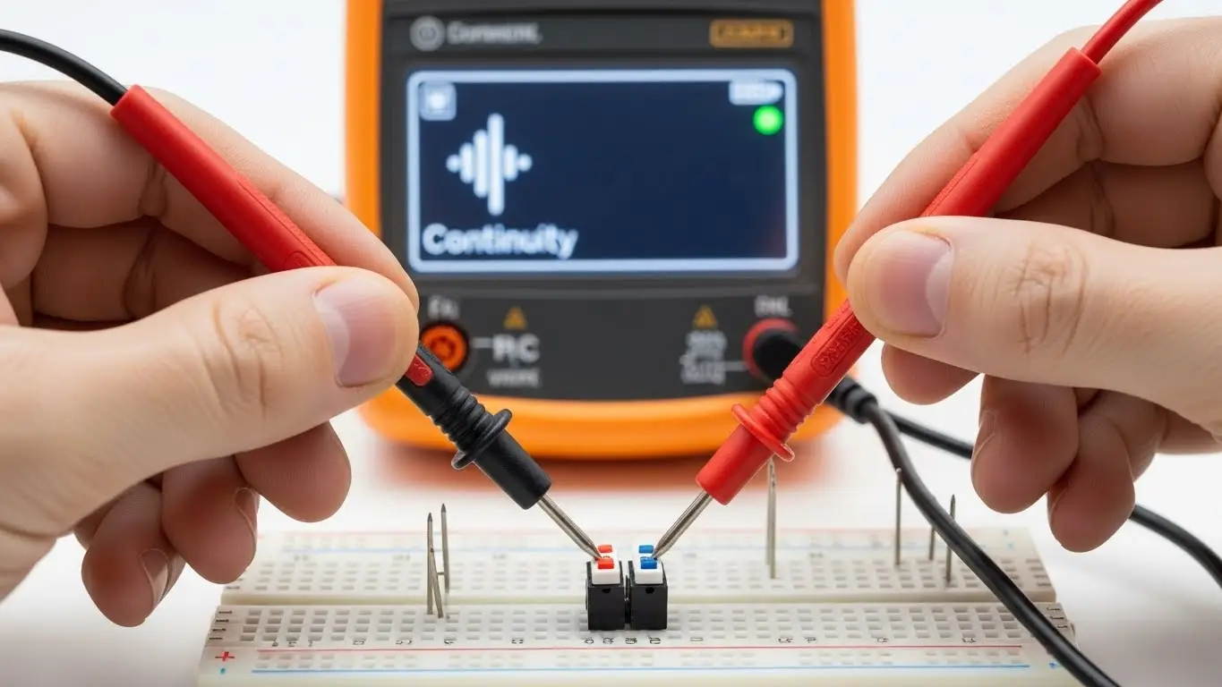
The Continuity Test
- Set Your Multimeter: Turn the dial to "Continuity Mode" (the sound wave icon).
- Test the "Always On" Pairs: Touch the probes to two pins on the same side.
- Beep: These pins are permanently connected (The Rail).
- No Beep: These are the switching pins.
- Test the "Switching" Action: Touch the probes to pins on opposite sides.
- No Beep (Default): Good. The switch is open.
- Beep (While Pressed): Good. The switch is working.
For a more detailed walkthrough of this process, including visual aids, check out our tutorial on the Simplest Way to Test a Tact Switch.
What Is the "Diagonal Rule" for Wiring?
If you are soldering a prototype and don't have a multimeter handy, you can use the Diagonal Rule.
The Strategy: Always connect your input wire to one corner (e.g., Top-Left) and your output wire to the opposite diagonal corner (e.g., Bottom-Right).
Why it works:
By crossing the body of the switch diagonally, you are mathematically guaranteed to cross from one rail to the other. You cannot accidentally connect to the same rail if you cross the center.
This technique is essential when building prototypes. You can see practical examples of this wiring in our guide to Tactile Switches in Microcontroller Projects.
Comparison: Standard 4-Pin vs. 2-Pin vs. SMD
Not all tact switches look the same. Here is how the pinouts compare across different styles you might find in the HX Switch catalog.
| Switch Type | Pin Count | Pinout Logic | Best Use Case |
| Standard THT | 4 | Pairs 1-2 and 3-4 connected. | Prototyping, Breadboards. |
| 2-Pin THT | 2 | Simple In/Out. No confusion. | tight PCB layouts. |
| SMD (Gull Wing) | 4 | Same as Standard THT. | Automated Assembly. |
If you are unsure which package type fits your specific board design, review our article on What Beginners Should Know About PCB Switches.
Common Pitfalls: Why Is My Switch Not Working?
Even if you identify the pins correctly, the circuit might fail. Here are two insights based on our engineering experience at HX Switch.
1. The Floating Pin (The Ghost Signal)
Identifying the pinout is useless if you don't anchor the signal. If you connect one pin to an Arduino and the other to nothing (expecting it to be "Off"), the pin will "float" and read random values. You must use a pull-up or pull-down resistor.
- Learn more: How Switches Control Logic Levels
2. Flux Wicking (The Phantom Short)
Expert Insight: In cheap, unsealed switches, soldering flux can wick up the legs and enter the housing. This conductive fluid bridges the gap between the rails internally. The result? The switch acts like it is pressed even when it isn't.
- The Fix: Use sealed switches from reputable brands like HX Switch for industrial applications. Compare this to DIP switch issues in our DIP Switch Basics for New Engineers guide.
Frequently Asked Questions
No, standard tact switches do not have polarity. They are simple mechanical devices that bridge a connection. You can connect your voltage to Pin 1 and ground to Pin 3, or vice versa. It will work exactly the same way.
On a rectangular tact switch (e.g., 6x3mm), the pins usually exit from the longer sides. On a square switch (6x6mm), looking at the bottom, the pins are often spaced differently (e.g., 4.5mm x 6.5mm). The side with the wider gap between pins is usually the side across the open circuit.
No, they serve different purposes. A tact switch is momentary (returns to off when released) and is used for inputs. A DIP switch is latching (stays off/on) and is used for configuration. Using a tact switch for configuration would require the user to hold the button down forever.
Learn more: How DIP Switches Are Used in Basic Electronics.
Nothing bad happens, but nothing useful happens either. Since Pins 1 and 2 are already connected internally, adding an external wire between them just creates a redundant path. The switch will not function as a switch.
Generally, no. The logic remains the same (pairs connected). However, the physical footprint is different. Always check the HX Switch datasheet for the specific pad layout before designing your PCB.
Key Takeaways
- The 4-Pin standard: Pins on the same longitudinal side are always connected.
- Diagonal Rule: Connect opposite corners to guarantee a correct circuit.
- No Polarity: You can wire input/output in either direction.
- Check Integrity: Cheap switches can suffer from internal flux shorts; use high-quality components for reliable pinout readings.
For critical applications where failure is not an option, verify your pinouts and choose rugged components. Explore our Industrial Switches Comprehensive Guide for heavy-duty options.