How to Configure DIP Switch Positions
To configure DIP switch positions, you manually toggle individual levers (actuators) on the switch block to a specific "ON" (closed) or "OFF" (open) state. This physical configuration creates a unique binary code that the device’s microcontroller reads to determine settings such as device addresses, operational modes, or communication frequencies. Typically, you use a small tool or stylus to move the switches. The configuration must usually match a receiver or specific manual setting, and for most devices, the power should be cycled (turned off and on) for the new switch positions to take effect.
What Do DIP Switch Positions Mean?
DIP (Dual In-line Package) switches act as a hardware-based interface for inputs. Unlike software menus, these provide a permanent, visual way to set parameters. Understanding the logic behind the positions is crucial for proper configuration.
Most DIP switches function on binary logic. Each switch in the bank represents a "bit." When a switch is flipped to the ON position, it usually corresponds to a binary 1. When it is in the OFF position, it corresponds to a binary 0.
The Binary Value System
In scenarios like setting a DMX address or a remote control frequency, each switch position holds a specific numerical value.
| Switch Number | Binary Value (if ON) | Description |
| 1 | 1 | The Least Significant Bit (LSB) |
| 2 | 2 | |
| 3 | 4 | |
| 4 | 8 | |
| 5 | 16 | |
| 6 | 32 | |
| 7 | 64 | |
| 8 | 128 | The Most Significant Bit (MSB) |
If you turn on Switch 1 and Switch 3, the value is 1 + 4 = 5.
How to Read ON and OFF Labels?
To determine the state of a DIP switch, look for markings on the switch body. "ON" is almost always labeled clearly. If the actuator is pushed toward the "ON" text, the circuit is closed (1). If it is pushed away, or toward a number/label like "OPEN," the circuit is open (0).
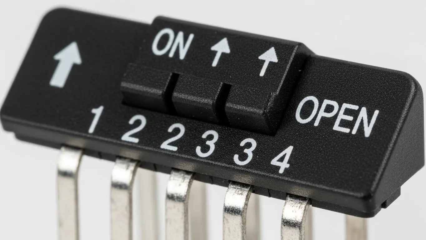
It is common to find the text "OPEN" printed on the unit. In electronics, an "Open" switch is disconnected (OFF). Therefore, if the switch is down on the "OPEN" side, it is OFF.
Step-by-Step: How to Configure a DIP Switch for Devices
Configuring these switches requires precision. Whether you are syncing a garage door opener or setting up an industrial sensor, the process involves physical verification and safety steps.
1. Identify the Target Configuration
Consult your device manual or the "Master" unit. For garage remotes, you must match the pattern inside the remote to the pattern on the motor unit exactly. For industrial equipment, you are often assigning a unique "Slave ID" (e.g., Address 1, 2, or 3).
2. Prepare the Environment
Ensure the environment is clean and stable. If you are integrating this component into a new control panel, you should review a proper industrial switch installation guide to ensure the mounting is secure and vibration-resistant before configuring the settings.
3. Toggle the Switches
Using a non-conductive tool, move the actuators.
- Slide DIP: Push the nub firmly until it clicks into position.
- Rocker DIP: Press the recessed side down to flip the switch.
4. Verify and Power Cycle
Once the pattern matches your requirements, power up the device. If the device was already on, you must turn it off and back on. Most microcontrollers only read the DIP switch state during the boot-up sequence.
Can I Configure DIP Switches on a PCB?
Yes, DIP switches are specifically designed for PCB (Printed Circuit Board) mounting. They are soldered directly onto the board to provide semi-permanent settings that a user can change without soldering tools.
When working with PCB-mounted switches, handling is critical. If you are replacing a switch or building a new board, the soldering process is similar to other small components. You can learn more about the nuances of soldering small form-factor switches in our guide on how to install a tact switch on PCB, as the principles of heat management and flux application apply to DIP packages as well.
Do I Need to Power Down Before Changing Switches?
Yes, you should always power down the device before changing DIP switch positions. While the switch itself is mechanical and won't be damaged by switching under load (usually), the device logic might not register the change, or undefined states could cause glitches.
Why Hot-Switching is Risky
- Latch-up: The software might read the state halfway through your adjustment, loading a corrupt setting.
- Short Circuits: In rare cases, using a conductive tool (like a metal screwdriver) on a live board can short adjacent pins.
- Initialization: As mentioned, many IoT and industrial devices only check the "Hardware Config" register during the startup phase (Setup Loop).
Frequently Asked Questions
The difference is the number of individual switches (bits) available. A 4-pin (or 4-position) switch allows for 16 unique combinations ($2^4$), while an 8-position switch allows for 256 unique combinations ($2^8$), offering much more granularity for addresses or codes.
This usually happens for two reasons: either the pattern does not exactly match the receiver, or the logic is inverted (some brands consider "Up" as ON, while others consider "Down" as ON). Try reversing the pattern if an exact match fails.
Yes, but they are durable. Standard DIP switches are rated for roughly 1,000 to 3,000 cycles. Since they are intended for "set-and-forget" configurations, this lifespan is usually sufficient for the life of the product.
"Floating" occurs when a switch is OFF but not connected to a ground reference, causing the signal to bounce between 0 and 1 randomly. This is why pull-up or pull-down resistors are required (either built-in or external) to ensure a clean OFF signal.
Key Takeaways
- Binary Basics: DIP switch positions generally represent binary numbers (1, 2, 4, 8) used for addressing or coding.
- Power Cycle: Always restart your device after changing positions; changes rarely take effect in real-time.
- Match the Master: For remotes and comms, the switch pattern must identically match the receiver or gateway.
- Gentle Handling: Use plastic tools to avoid shorting circuits or damaging the small plastic actuators.
Conclusion
Correctly configuring DIP switch positions is a fundamental skill for managing hardware without complex software interfaces. By understanding the binary values and ensuring you power cycle your device, you can troubleshoot and set up electronics with confidence. Whether you are securing a garage door or commissioning an industrial sensor, the physical "click" of a DIP switch remains the standard for reliable configuration.