How to Assemble Tact Switches on SMD Boards
How to assemble a tact switch on smd board is a precision skill that separates professional electronics manufacturing from amateur tinkering. Getting this right ensures your device provides that satisfying, crisp "click" for years, while a poor assembly leads to intermittent failures and frustrated users.
In my years managing production lines and hand-assembling prototypes, I have seen thousands of boards fail simply because the tact switch wasn't seated flush or the reflow profile was too hot, melting the internal dome. It is not just about melting solder; it is about mechanical stability. Let's walk through the exact process to get a perfect bond every time.
What Is the Core Challenge of SMD Tact Switch Assembly?
The main challenge in assembling SMD tact switches is balancing precise mechanical placement with thermal management. Unlike passive components like resistors, tact switches have moving mechanical parts and plastic housings that are sensitive to heat. You must achieve a strong solder fillet for mechanical durability without contaminating the internal contact mechanism with flux or damaging the housing with excessive heat.
The Mechanics of Surface Mount Assembly
When you mount a resistor, it sits there. When you mount a tact switch, it gets hammered. Every time a user presses that button, they apply shear force to your solder joints.
I recall a project for a handheld industrial controller where we saw a 15% field failure rate within six months. The issue wasn't the switch quality; it was the assembly. The solder paste stencil was too thin, creating weak joints that cracked under repetitive thumb presses. We adjusted the stencil aperture to deposit 20% more paste, and the failures vanished.
This mechanical stress is why understanding the broader context of installation is vital. For a high-level view of ruggedizing these inputs, review our Industrial Switch Installation Guide.
What Tools Are Essential for SMD Tact Switch Assembly?
To assemble SMD tact switches professionally, you need fine-tip tweezers, tacky flux, a soldering station with temperature control, and high-quality solder paste or wire. For volume assembly, a reflow oven and a stainless steel stencil are required. If reworking by hand, a hot air rework station is indispensable for evenly heating the pads without melting the plastic switch body.
Selecting the Right Equipment
You cannot bluff your way through Surface Mount Device (SMD) assembly with a plumber's soldering gun.
- Tweezers: Use anti-static, curved tweezers (ESD-15 type). Tact switches are often taller than they are wide, making them prone to slipping.
- Magnification: A microscope or a 10x loupe is non-negotiable. You need to see if the switch feet are perfectly aligned with the pads.
- Flux: Use "No-Clean" tacky flux. Liquid flux tends to flow inside the switch mechanism (capillary action), which ruins the click feeling.
- Solder: For SMD, 63/37 leaded is easier to work with, but SAC305 (Lead-Free) is the industry standard.
For a deeper dive into the specific soldering techniques required for these components, I highly recommend reading our dedicated guide on how to solder SMD tact switches.
How Do You Prepare the PCB Footprint?
Preparation involves cleaning the PCB pads with isopropyl alcohol and ensuring the land pattern matches the switch datasheets exactly. Before applying paste or heat, verify that the pads are free of oxidation and that the solder mask does not encroach on the soldering area, which can cause the switch to sit unevenly and "rock" when pressed.
The Foundation of a Good Joint
I once spent a day debugging a batch of boards where the switches felt "mushy." It turned out the PCB designer had made the pads 0.5mm too narrow. The switch was physically sitting on the solder mask rather than the metal pad, preventing it from sitting flat.
Before you pick up a soldering iron, double-check your CAD files. If you are in the design phase, or if you are troubleshooting why a switch won't sit flat, consult our article on Tact switch PCB footprint design. Getting the footprint right prevents "tombstoning," where the component stands up vertically during reflow due to uneven wetting forces.
How to Apply Solder Paste Correctly?
Apply solder paste using a stainless steel stencil to ensure uniform deposition height and volume across all pads. If assembling manually without a stencil, use a syringe dispenser to apply a small "grain of rice" amount of paste to each pad. Avoid over-application, as excess solder can bridge pins or wick up into the switch mechanism, rendering it useless.
Managing Paste Volume
The "Goldilocks" zone for solder paste is critical for switches.
- Too Little: The joint will crack under mechanical pressure (the user pressing the button).
- Too Much: The switch will float on a pool of solder, misaligning it. Or worse, solder balls will form and short out adjacent pins.
Pro Tip: If you are hand-applying paste, dispense it on the pads, not the switch legs. This allows you to verify coverage before placing the component.
How to Place the Tact Switch Accurately?
Place the tact switch gently onto the paste using tweezers or a vacuum pickup tool, applying just enough pressure to seat the leads into the paste. Ensure the alignment is precise; unlike smaller passive components, the surface tension of molten solder is often not strong enough to self-align a heavy, bulky tact switch if it is placed significantly off-center.
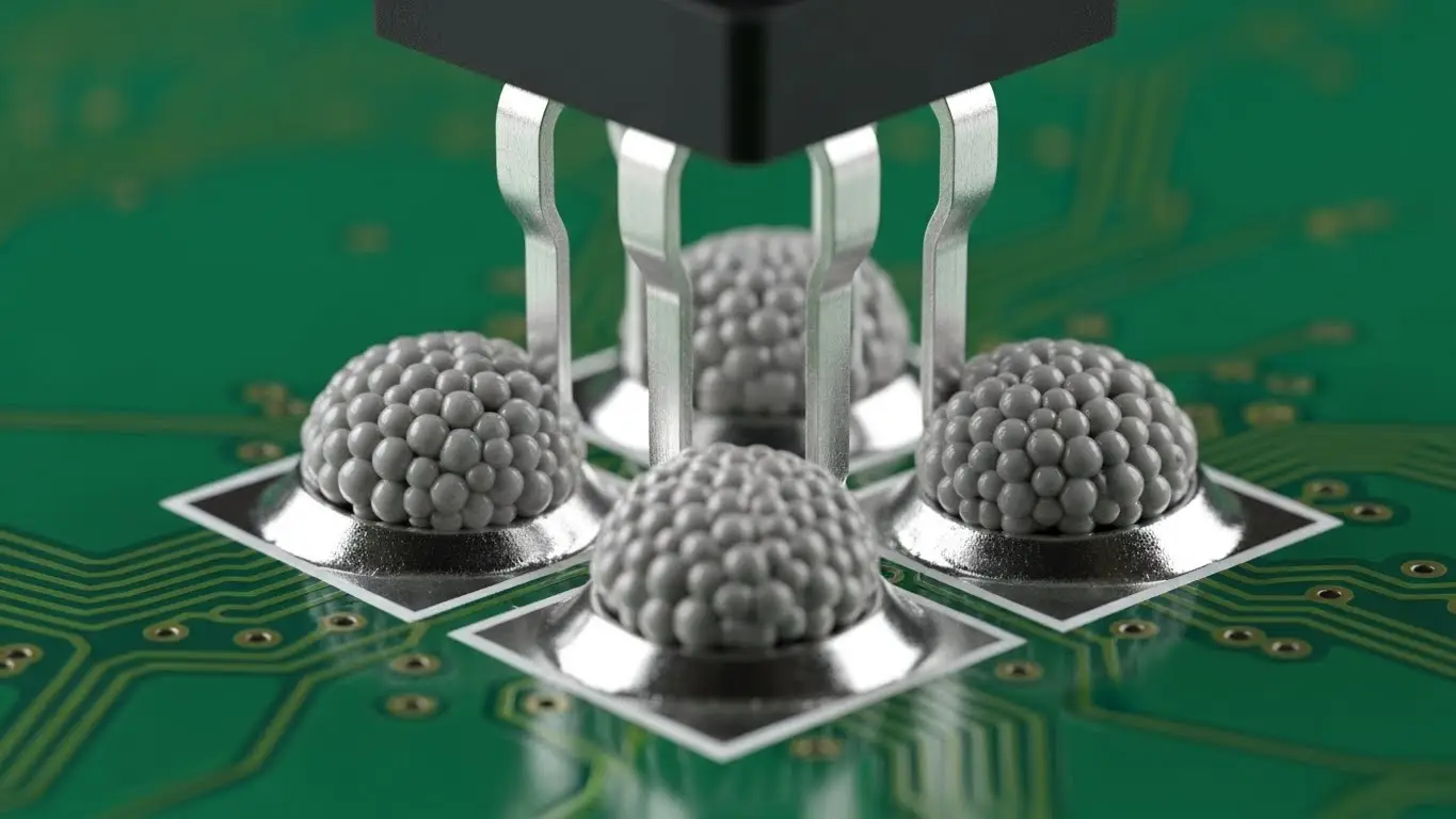
The "Tap" Technique
When I place a switch, I give it a tiny, vertical tap—not a squash. You want to ensure the leads are touching the paste but not squishing the paste out sideways.
- Orientation: Check the polarity. While many tact switches are normally open (NO) and symmetrical, some illuminated versions have specific anode/cathode orientations.
- Flatness: Look at the board from the side (eye level). Is the switch tilting? If so, remove it, clean the pads, and start over. You cannot fix a tilted switch during reflow.
For general tips on placing these components, whether through-hole or surface mount, refer to how to install tact switch on PCB.
What Is the Proper Reflow Profile for Tact Switches?
The proper reflow profile typically involves a preheat zone (150°C), a soak zone, and a peak temperature around 245°C-260°C (depending on solder type), strictly limited to 10-20 seconds. Because tact switches contain plastic and rubber membranes, you must adhere to the manufacturer's "temperature vs. time" graph to avoid melting the internal actuator.
Surviving the Oven
This is where the magic (or the disaster) happens. I’ve seen switches come out of an oven looking fine, but the internal dome had lost its "snap" because the soak time was too long.
- Soak Zone: This activates the flux and removes volatiles. Keep this steady to avoid thermal shock.
- Reflow Zone: Get in and get out. You want the solder to wet, but you don't want to cook the plastic.
- Cooling: Rapid cooling helps form a fine-grain, strong solder structure.
If you are using a hot air station manually, keep the nozzle moving. Never point it directly at the plastic button center; aim at the leads.
How Do You Inspect and Test the Assembly?
Inspect the solder fillets for a smooth, concave "ramp" shape and verify mechanical actuation by clicking the switch. Electrically, use a multimeter in continuity mode to ensure the switch closes the circuit only when pressed. Check for solder bridges between pins and verify that no flux residue has entered the switch body.
Quality Control Checklist
After the board cools, I perform a three-step check:
- Visual: Use a microscope. Are the heels of the leads wetted? Is there a nice fillet at the toe?
- Tactile: Press it. Does it click? If it feels sticky or silent, flux may have entered the housing.
- Electrical: Connect a multimeter. This process is very similar to checking DIP switches. If you aren't sure about the testing workflow, read how to test dip switch with multimeter. The logic of testing continuity is identical.
How Do You Handle Mixed-Technology Boards?
When assembling boards with both tact switches and DIP switches, assemble the SMD components (tact switches) first via reflow, then hand-solder the through-hole components (DIP switches) afterward. This prevents the through-hole components from interfering with the stencil printing process or being damaged by the reflow oven's heat.
Logic and Layout
Often, a board will have a tact switch for a "Reset" function and a DIP switch for "Configuration."
- Process Order: Solder Paste -> Place Tact Switch -> Reflow -> Insert DIP Switch -> Wave Solder/Hand Solder.
If your board includes configuration switches, you need to ensure they are set correctly before final assembly into the housing. Ensure you understand how to configure DIP switch positions so you don't deliver a device in the wrong mode. Furthermore, if the board is complex, knowing how to read DIP switch settings is crucial for final quality assurance (QA) checks.
Troubleshooting Common Assembly Defects
Common defects include "floating" switches (uneven seating), solder bridging (shorts), and cold joints (dull, grainy solder). To fix a floating switch, apply hot air to reflow both sides simultaneously and gently press down with tweezers. For bridges, apply flux and use solder wick to remove excess material.
The "Sticky Button" Syndrome
This is the most frustrating defect. It happens when flux gets inside.
- Cause: Using liquid flux too liberally or washing the board with a solvent that is not switch-safe.
- Fix: Unfortunately, usually replacement. You cannot easily clean the inside of a sealed micro-switch.
Summary of Assembly Specs
| Parameter | Specification | Why it Matters |
| Pad Size | Manufacturer Rec. + 10% toe | Allows for strong mechanical fillet. |
| Stencil Thickness | 0.12mm - 0.15mm | Ensures enough solder for mechanical strength. |
| Reflow Peak | 245°C (Lead-Free) | Melts solder without melting plastic housing. |
| Flux Type | No-Clean ROL0 | Prevents internal corrosion and sticking. |
Export to Sheets
By mastering how to assemble a tact switch on smd board, you ensure the reliability of the primary user interface of your product. Take your time with the paste, watch your heat profile, and always verify that satisfying "click."
Frequently Asked Questions (FAQ)
Yes, you can use a fine-tip soldering iron. Tin one pad on the PCB first, slide the switch into place while heating that pad to anchor it ("tacking"). Then, solder the remaining legs carefully. It requires steady hands but is very effective for prototypes.
This usually happens if liquid flux wicked inside the switch mechanism or if the reflow temperature was too high, deforming the internal plastic dome. Always use "no-clean" gel flux sparingly and adhere strictly to the manufacturer's temperature profile.
For most applications, a SAC305 (Sn96.5/Ag3.0/Cu0.5) lead-free paste is standard. However, for manual hobbyist assembly, a leaded 63/37 paste has a lower melting point (183°C vs 217°C), which reduces the risk of melting the plastic switch body.
Do not force it. Apply plenty of flux to all pins. Use a hot air rework station to heat all pads simultaneously until the solder flows. Gently nudge the switch into alignment with tweezers, then remove the heat and hold it steady until the solder solidifies.