How Switches Control Logic Levels
Switches control logic levels by physically connecting a microcontroller’s input pin to either a high voltage source (Logic 1) or a ground reference (Logic 0). However, simply connecting a wire isn't enough; you must ensure the signal is stable, clean, and unambiguous.
In digital electronics, there is no "maybe." A pin must be definitely On (High/VCC) or definitely Off (Low/GND). Mastering this binary state is the first step in moving from basic circuits to intelligent, programmable devices.
The "Floating" Problem: Why You Can't Just Connect Two Wires
If you connect a tactile button between an Arduino pin and 5V, the microcontroller will read "HIGH" when you press it. But what happens when you let go?
You might assume it reads "LOW" (0V), but it doesn't.
When the switch is open, the pin is connected to nothing. In electronics, this is called a Floating Pin. A floating pin acts like a tiny radio antenna, picking up electromagnetic interference from your hand, the room lights, or nearby wires. The microcontroller will read random 1s and 0s, causing your device to glitch unpredictably.
To fix this, we need to "anchor" the voltage when the switch is open. We do this with resistors.
The Solution: Pull-Up vs. Pull-Down Resistors
To force a floating pin to a known state, we use a resistor to weakly connect it to either voltage or ground.
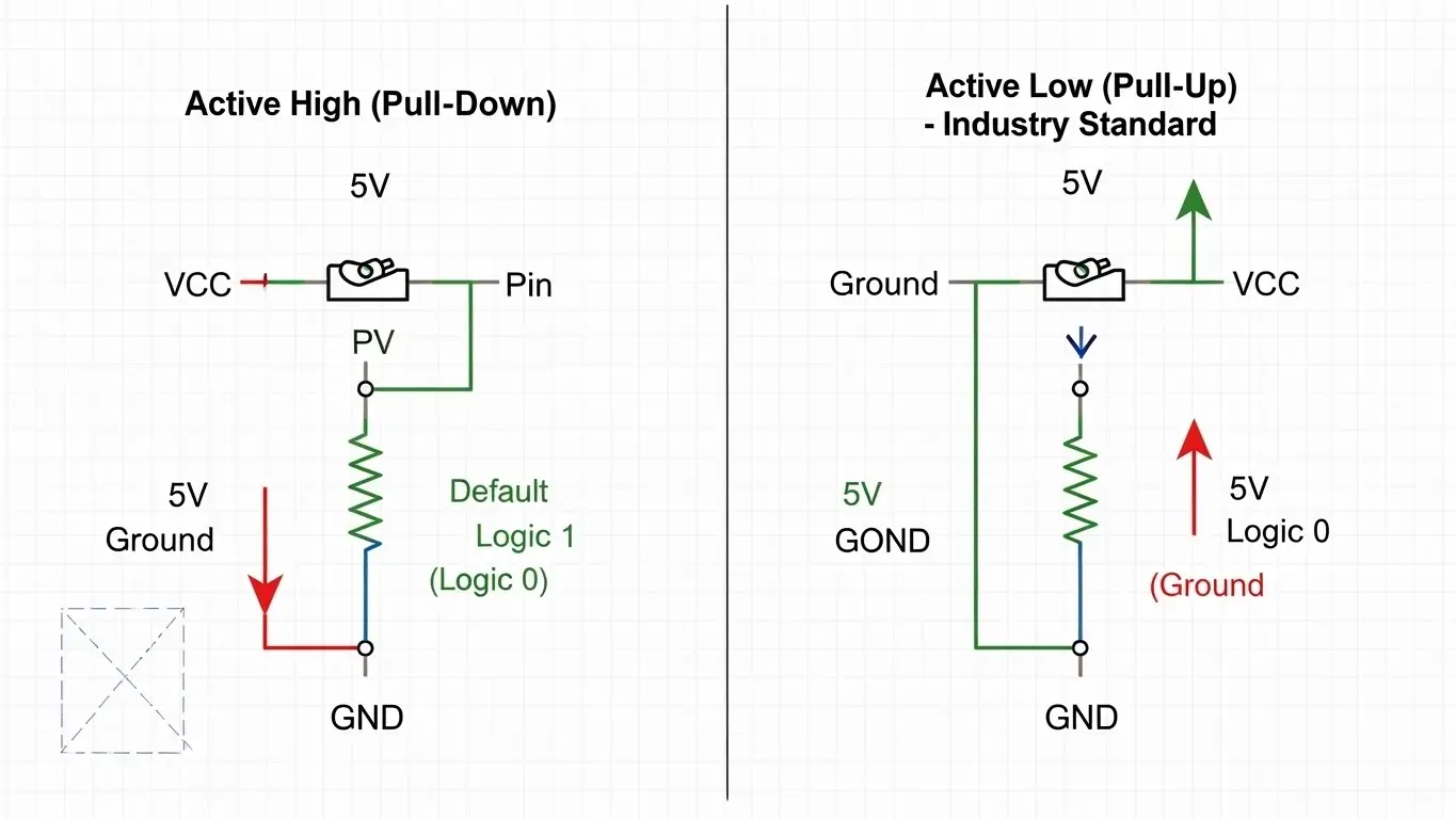
1. Pull-Down Resistor (Active High)
In this configuration, a resistor connects the pin to Ground (0V).
- Default State: The resistor holds the pin LOW (0).
- Pressed State: The switch connects the pin to 5V (HIGH).
- Logic: Pressing the button = Logic 1.
- Verdict: Intuitive for beginners, but less common in professional hardware.
2. Pull-Up Resistor (Active Low)
In this configuration, a resistor connects the pin to Voltage (3.3V or 5V).
- Default State: The resistor holds the pin HIGH (1).
- Pressed State: The switch connects the pin to Ground (0).
- Logic: Pressing the button = Logic 0.
- Verdict: The industry standard. Most microcontrollers have internal pull-up resistors you can enable in code, saving you from adding external parts.
Active Low: Why Is "Pressed" Equal to Zero?
Beginners often find "Active Low" logic confusing. Why would we want a button press to send a "0"?
It comes down to safety and noise immunity. Ground is the most stable reference point in a circuit. By connecting your switches to Ground (Active Low), you reduce the risk of accidental short circuits carrying live voltage if a wire comes loose.
For a deeper dive into how this logic applies to setting permanent device addresses, read our Beginner’s Guide to DIP Switch Configuration.
Hardware Implementation: Tactile vs. DIP
How you physically arrange your switches depends on their purpose.
Tactile Switches (Momentary)
For user input—like a reset button or a keyboard key—you generally use Active Low logic with an internal pull-up resistor.
- Component: Standard 4-pin Tact Switch.
- Setup: Connect one side to the GPIO pin, the other to Ground.
- Learn More: Understand the mechanics of these buttons in our Introduction to Tact Switches.
DIP Switches (Latching)
For configuring settings—like a garage door frequency or a sensor ID—you need a state that persists. DIP switches often use external pull-up resistor networks (arrays) to ensure all 8 pins stay HIGH until a switch is flipped LOW.
- Component: 8-Position DIP Block.
- Setup: Used to create binary addresses (e.g., 10110010).
- Context: See how these are integrated into larger boards in our guide on How DIP Switches Are Used in Basic Electronics.
Troubleshooting: Why Is My Switch "Bouncing"?
Even with perfect logic levels, a switch might trigger multiple times with a single press. This is called Switch Bounce.
When metal contacts slam together, they vibrate microscopically, creating a rapid-fire series of On/Off signals before settling. To the microcontroller, one press looks like 15 presses in 2 milliseconds.
How to Fix It:
- Hardware: Add a small capacitor (0.1µF) across the switch to smooth the voltage spike.
- Software: Add a small delay (e.g., 50ms) in your code to ignore the noise immediately after a signal change.
If you aren't sure if your switch is bouncing or simply broken, you should verify the mechanism itself. We have a guide on the Simplest Way to Test a Tact Switch using a multimeter.
Designing for Harsh Environments
If you are designing a PCB for a factory or outdoor use, standard logic levels might not be enough. Electrical noise from motors can trigger false signals even with pull-up resistors.
In these cases, you need stronger pull-ups (lower resistance values, like 1kΩ instead of 10kΩ) and better isolation. For a complete overview of ruggedizing your inputs, refer to our Industrial Switches Comprehensive Guide.
Frequently Asked Questions
In a 5V system, Logic 1 (High) is typically anything above 3V, and Logic 0 (Low) is anything below 1.5V. The "undefined" zone in the middle is where floating pins often drift, causing errors.
Only if your microcontroller has "Internal Pull-Ups" enabled. If not, you absolutely need an external resistor; otherwise, the input will float, and your data will be garbage.
10kΩ is the "Goldilocks" value. It is low enough to hold the pin voltage firmly but high enough to limit current waste when the switch is pressed.
Active Low is generally better for noise immunity and is the standard for most internal microcontroller inputs. Active High is more intuitive for beginners but requires external resistors more often.
Electrically, they are the same. A "button" (Tact Switch) is momentary (returns to default when released), while a "switch" (Slide/DIP) latches (stays in position). You can read more about the physical differences in What Beginners Should Know About PCB Switches.
Key Takeaways
- Never Float: Always use a resistor (internal or external) to anchor your input pin.
- Active Low is Standard: Connecting switches to Ground is safer and more common than connecting to Voltage.
- Debounce is Mandatory: Mechanical switches always vibrate; plan for it in hardware or software.
- Know Your Voltage: Ensure your switch logic matches your board (3.3V vs 5V) to avoid damaging components.
Conclusion
Controlling logic levels is about more than just closing a circuit; it’s about defining a clear, noise-free state for your processor. By using pull-up resistors and understanding Active Low logic, you ensure your device behaves exactly as programmed, every single time.
Ready to build your circuit? Start by selecting the right component for the job from our guide on What Beginners Should Know About PCB Switches.