DIP Switches for Industrial Machines: The Complete Configuration Guide
DIP switches for industrial machines remain the undisputed standard for reliable, hardware-level device configuration. While software interfaces evolve, the need for a physical, fail-safe method to set addresses, baud rates, and operational modes on the factory floor has never disappeared. In this comprehensive guide, we strip away the basics and dive into the engineering principles, selection criteria, and maintenance protocols that keep industrial automation running smoothly.
What Are DIP Switches and Why Are They Critical for Industrial Automation?
DIP (Dual In-line Package) switches are manual electric switches packaged in a standard group, used primarily to customize the behavior of an electronic device for specific situations.
In an industrial context, reliability is currency. A DIP switch for industrial machines provides a distinct advantage: it offers "set-and-forget" permanence. Unlike software settings that can be wiped by a firmware update or a corrupted memory chip, a physical switch position is immune to code errors. They allow technicians to visually verify settings like Modbus addresses or termination resistance without powering up a laptop or connecting a diagnostic tool.
The "Hard-Coded" Advantage
I once worked on a legacy SCADA upgrade where a software glitch reset the communication baud rates on twenty remote terminal units (RTUs). The only units that stayed online were the ones using physical DIP switches for their network configuration. That experience taught me a valuable lesson: physical isolation equals security.
When a technician flips a rocker on a DIP switch, they are physically bridging or breaking a circuit. There is no software layer to interpret the command—it is purely electromechanical. This is why they remain prevalent in:
- Motor Drives (VFDs): Setting voltage inputs.
- Industrial Sensors: Configuring sensitivity ranges.
- Gateways: Defining master/slave relationships in RS-485 networks.
How Do You Choose the Right DIP Switch Type for Industrial Environments?
Selection depends on actuation method (slide vs. rotary), board real estate, and ease of access. You must balance the need for frequent adjustments against the risk of accidental changes.
Industrial environments are hostile. Vibration, dust, and human error are constant threats. Choosing the correct form factor is your first line of defense.
1. Slide DIP Switches (Standard)
These are the workhorses. They feature raised sliders that move linearly.
- Best for: Visual clarity. You can see the "ON/OFF" position from a distance.
- Drawback: Lower actuation density compared to rotary types.
2. Piano (Rocker) DIP Switches
These feature a side-actuated mechanism that resembles piano keys.
- Best for: Edge-of-PCB mounting. If your industrial controller sits inside a DIN rail enclosure, a piano switch allows access through a cutout without opening the casing.
- User Note: The lever action often requires less force than a flush slide switch, making them easier to adjust with gloves.
3. Rotary DIP Switches
Instead of multiple levers, a single dial rotates to select a binary code (BCD) or hexadecimal output.
- Best for: Space-saving. A single rotary switch can replace 4 standard slide switches (representing 16 positions).
- Use Case: Setting device IDs on a network where you need numbers 0-9 or 0-F.
| Feature | Slide Type | Piano Type | Rotary Type |
| Visibility | High (ON/OFF marked) | High (Side view) | Medium (Requires alignment) |
| Density | Low | Low | High |
| Accidental Actuation | Medium | Medium | Low (Requires screwdriver) |
| Sealing | Tape/Epoxy | Tape/Epoxy | O-Ring Internal |
How Important Are Contact Plating and Electrical Ratings?
Gold plating is essential for low-voltage/low-current logic applications to prevent oxidation, while self-cleaning wiping contacts ensure reliability in dusty environments.
Most DIP switches for industrial machines operate at "logic levels"—typically 5V or 3.3V at mere milliamps. This is where engineers often make mistakes. They assume a switch rated for 24V will work fine at 3V. Not always.
The Gold vs. Tin Debate
- Gold Flash/Plating: Gold is non-corrosive. For "Dry Circuits" (low voltage/current where no arc cleans the contact), gold is mandatory. It ensures the signal passes through even after sitting dormant for five years.
- Tin Plating: Cheaper and acceptable for higher currents where the arcing action cleans the oxide layer. However, in an industrial PLC rack running 5V logic, tin contacts can oxidize over time, leading to intermittent failures.
Engineering Rule of Thumb: If your circuit runs below 100mA/20V, specify gold contacts. The cost difference is negligible compared to the cost of downtime.
The Self-Cleaning Mechanism
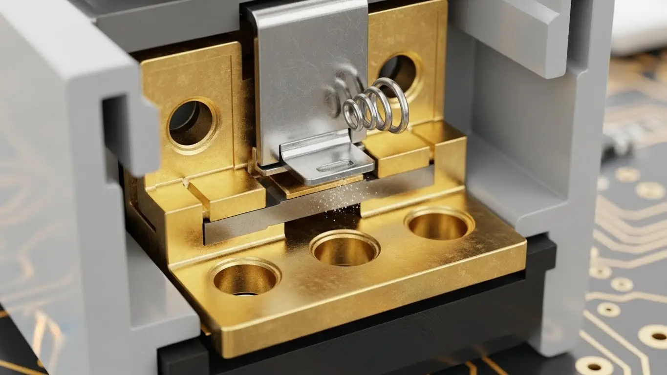
Look for switches with a "wiping" contact design. As the actuator moves, it physically slides across the fixed contact, scraping away dust or oxide buildup. This is critical in factories with high particulate matter (like textile or paper mills).
For a deeper dive into contact resistance and load specifications, referencing our technical switch application notes can prevent costly specification errors during the design phase.
What Are the Environmental Protection Requirements (IP Ratings)?
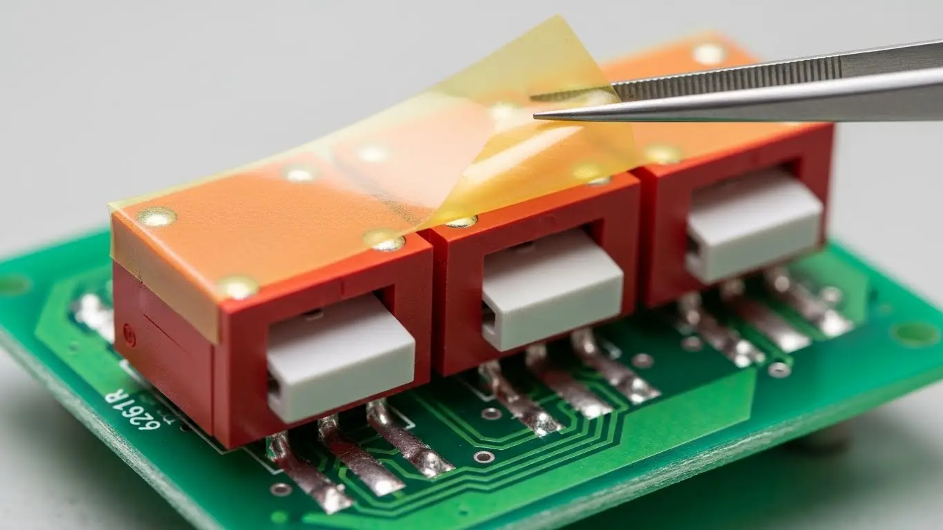
Industrial DIP switches typically require tape sealing during soldering to prevent flux ingress, and robust housing materials to withstand high operating temperatures and vibration.
A switch that fails in a climate-controlled server room is an annoyance. A switch that fails in a 60°C injection molding plant is a disaster.
1. Flux Contamination (The #1 Killer)
During the wave soldering process, flux can wick up inside the switch housing. Once it cools, it acts as an insulator.
- The Fix: Specify switches with "Top Tape Seal" or "Process Sealed." This removable tape protects the mechanism during the wash/solder phase. Do not remove the tape until the PCB is washed and dried.
2. Vibration Resistance
In heavy machinery, constant vibration can cause "contact chatter"—micro-interruptions in the signal.
- The Fix: High-pressure contact springs. Ensure the switch is rated for typical industrial vibration standards (e.g., MIL-STD-202).
3. Temperature Extremes
Standard plastic housings (PBT) handle up to 85°C. For automotive or heavy industrial use, look for high-temp nylons (PA66 or PA9T) or LCP (Liquid Crystal Polymer) that can withstand 105°C to 125°C.
DIP Switches vs. Other Input Methods: When to Use Which?
Use DIP switches for permanent hardware configuration; use tact switches for momentary user input; use jumpers for permanent, low-cost settings that rarely change.
It is vital to distinguish between configuration and interaction.
- DIP Switches: "Set it once." Used for baud rates, device addresses, and protocol selection.
- Tact Switches: "Press it now." Used for resets, menu navigation, or test triggers. If you are designing a user interface rather than a configuration panel, you should explore tact switches for consumer electronics for better haptics and ergonomics.
- Jumpers: "Set it forever." Cheaper than DIP switches but easily lost and harder to change in the field.
Comparison Table: Input Methods
| Criterion | DIP Switch | Tact Switch | Jumper Header |
| Function | Static Configuration | Momentary Input | Static Configuration |
| Durability | 2,000 - 5,000 Cycles | 100k - 1M+ Cycles | 50 - 100 Cycles |
| Field Service | Excellent (No tools) | Good | Poor (Easy to lose) |
| Cost | Medium | Low | Very Low |
Troubleshooting Common DIP Switch Failures in the Field
The most common failures are intermittent signals caused by oxidation on contacts, flux residue from manufacturing, or physical damage from using improper tools.
I recall a troubleshooting ticket for a CNC machine that kept dropping off the network. The culprit? A rotary DIP switch set to "Position 4" that wasn't quite detented. Vibration had jiggled it between 3 and 4.
Step-by-Step Diagnostic Protocol
- Visual Inspection:
- Is the actuator fully seated in the detent?
- Is there visible corrosion on the pins?
- Is the top tape seal still attached? (If so, remove it; it can trap moisture over time).
- Continuity Check:
- Power down the machine.
- Set your multimeter to continuity/resistance mode.
- Measure across the switch terminals.
- Good Reading: < 50 milliohms (0.05 ohms).
- Bad Reading: > 1 ohm or fluctuating.
- The "Exercise" Fix:
- If the reading is high, cycle the switch back and forth 10-20 times. This engages the self-cleaning wiping action and often restores the connection by scraping off the oxide layer.
Installation Best Practices for Long-Term Reliability
Ensure proper soldering temperature profiles to prevent plastic deformation, and position switches away from high-heat components or heavy vibration sources on the PCB.
Soldering Guidelines
- Hand Soldering: Max 350°C for 3 seconds. Apply heat to the terminal, not the switch body.
- Wave Soldering: Preheat 100°C max. Solder bath 260°C max for 5 seconds. Top tape seal is mandatory here.
PCB Layout Strategy
Don't place dip switches for industrial machines next to the massive transformer or the heat sink of a power transistor. The thermal cycles can warp the plastic housing, changing the contact pressure. Furthermore, ensure there is "finger space." If you bury the switch between two tall capacitors, a field tech will be forced to use a screwdriver to change it, increasing the risk of slipping and gouging the PCB.
The Future of DIP Switches in Industry 4.0
Despite the rise of software-defined networking (SDN) and IoT, DIP switches remain essential for "Day Zero" provisioning and fail-safe hardware overrides.
You might hear that DIP switches are obsolete. This is false. In the era of Industry 4.0 and IoT, the "Edge" needs security. A software hacker can rewrite a configuration file remotely. They cannot physically flip a DIP switch inside a locked control cabinet.
Key Trends:
- Hybrid Systems: Devices that use DIP switches to set a static IP address for initial setup, after which software takes over.
- Miniaturization: Half-pitch (1.27mm) DIP switches are becoming standard for high-density IoT sensors, replacing the traditional 2.54mm pitch.
Conclusion: The "Set and Forget" Standard
When specifying DIP switches for industrial machines, you are not just buying a component; you are buying peace of mind. Whether it’s a 4-position slide switch for a garage door opener or a 16-position rotary switch for a nuclear plant controller, the principles remain the same: Quality contacts (gold), robust sealing (tape/IP rating), and accessible placement.
Don't let a $0.50 component be the reason a $50,000 machine goes offline. Choose wisely, install correctly, and your configuration will hold fast against the test of time.
Frequently Asked Questions (FAQ)
While common, it is risky. Metal screwdrivers can slip and damage the PCB traces or the switch housing. It is better to use a dedicated plastic adjustment tool or a non-conductive stick, especially if the board is live (hot).
The standard pitch (distance between pins) is 2.54mm (0.1 inch), matching standard breadboards and IC sockets. "Half-pitch" switches are 1.27mm (0.05 inch) and are used in space-constrained modern devices. Ensure your PCB footprint matches the switch pitch.
The tape seal protects the internal contact mechanism from flux, solvents, and water wash processes during PCB assembly. You should peel this tape off after the board is assembled and dried to allow the switch to cool and operate normally, although leaving it on in dusty environments can offer some dust protection (if it doesn't interfere with actuation).
Industrial DIP switches are typically rated for 2,000 to 5,000 mechanical cycles. This is much lower than a tact switch (1M cycles) because DIP switches are designed to be set once and rarely changed.
Piano (or side-actuated) switches are used when the switch is mounted on the edge of a board, allowing users to flip the switches from the side rather than from above. This is ideal for devices mounted in racks or DIN rails where top access is blocke.