DIP Switch Reading Errors — Troubleshooting Guide
DIP switch reading errors typically stem from three root causes: mechanical failure (oxidation, dust, or wear), human error (misinterpreting labels or binary values), or logical faults (reading the switch at the wrong time). To fix this, first verify that the physical position matches the "ON" label. If the setting is correct but the device fails to respond, power cycle the unit, as most industrial controllers and microcontrollers only read switch states during the initial boot sequence. Finally, if the issue persists, use a multimeter to check for electrical continuity across the contacts. Addressing these basics resolves nearly 90% of configuration issues in industrial and consumer electronics.
Why Is My Device Not Recognizing the DIP Switch Settings?
The most common reason for this error is changing the switch position while the device is powered on. Most devices do not "poll" (check) the DIP switches continuously; they only read the configuration once during startup.
The "Read-Once" Logic
In many industrial applications, the software reads the GPIO pins connected to the DIP switch immediately after power is applied. If you flip a switch from "Address 1" to "Address 2" while the machine is running, the software won't notice the change until you restart it.
Always follow a strict protocol: Power Down -> Change Settings -> Power Up. This is a fundamental step often covered in broader Industrial Switch Installation Guide documentation. If you skip the restart, you are essentially ghost-editing a configuration that the processor ignores.
How Do I Know If a DIP Switch Is Bad?
You can identify a faulty switch by performing a continuity test with a multimeter. If the switch is physically in the "ON" (closed) position but the meter shows high resistance (OL) or fails to beep, the internal contact is likely corroded, dirty, or broken.
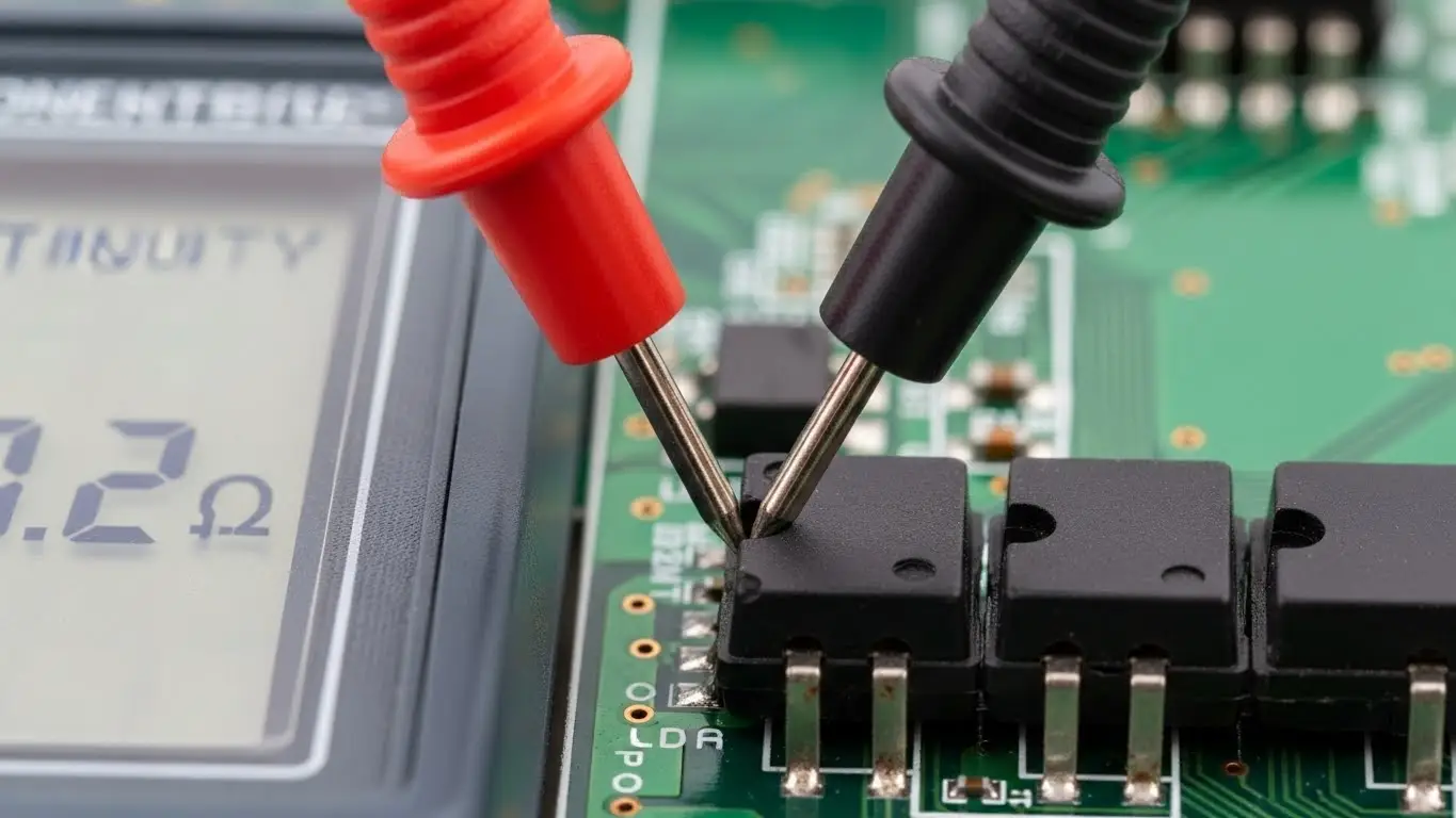
Testing for Internal Failure
Physical switches operate in harsh environments. Over time, the gold or silver plating on the internal wipers can oxidize, or dust can settle between the contacts, creating an open circuit even when the actuator is pushed to "ON."
To verify this, you need to isolate the switch from the power source and test the resistance. We have a detailed walkthrough on this procedure in our article on how to test a DIP switch with a multimeter.
Data Table: Resistance Values Guide
| Meter Reading | Switch Position | Diagnosis | Action |
| 0.0Ω - 0.5Ω | ON (Closed) | Healthy | No action needed. |
| > 1.0Ω | ON (Closed) | Dirty/Oxidized | Cycle switch 10x to clean; replace if fails. |
| OL (Infinity) | ON (Closed) | Broken Internal | Replace component immediately. |
| 0.0Ω | OFF (Open) | Shorted Internal | Replace component immediately. |
[Image Suggestion: A close-up photo of a multimeter probe touching the legs of a DIP switch on a green PCB, showing a reading on the screen. Alt Text: Technician testing DIP switch continuity with a digital multimeter.]
Are You Misreading the Binary Code or Labels?
Human error accounts for a significant portion of "reading errors," specifically confusing "ON/OFF" orientation or miscalculating binary sums. Manufacturers are not consistent; some define "Up" as ON, while others define "Down" as ON.
The Orientation Trap
Never assume "Up" is "On." Always look for the microscopic text printed on the plastic housing.
- Label Check: Look for "ON," "OPEN," or a standard arrow.
- Numbering: Ensure you are reading the switch order correctly (1 through 8). Sometimes Switch 1 is the Least Significant Bit (LSB), and sometimes it is the Most Significant Bit (MSB).
If you are calculating addresses (e.g., for DMX or networking), a simple addition error can make the device invisible to the system. You can refresh your knowledge on the math behind the hardware in our guide on how to read DIP switch settings.
Can Improper Soldering Cause Signal Errors?
Yes, cold solder joints or "flux wicking" can insulate the switch pins, preventing the electrical signal from reaching the PCB. If flux enters the switch housing during assembly, it can coat the contact surfaces, rendering the switch electrically dead despite mechanical actuation.
Flux Contamination and Cold Joints
DIP switches are not hermetically sealed. If you use excessive liquid flux or submerge the board during cleaning, the contaminants can seep inside via capillary action. This is a common manufacturing defect.
Furthermore, if the solder joint is "cold" (looks dull and grainy), it may not be making a true electrical connection. The principles of precision heating are critical here. While often associated with smaller components, the techniques detailed in how to solder SMD tact switches apply equally to rework on DIP switches: heat the pad and the lead simultaneously to ensure wetting.
Can PCB Design Flaws Affect Switch Readings?
If the PCB footprint is incorrect, the switch may not seat flat, leading to mechanical stress that breaks the internal connection over time. A switch that rocks back and forth when pressed will eventually fail at the solder joints or the internal wiper.
The Importance of Seating
When a component "floats" above the board due to a mismatched land pattern, the actuation force is transferred to the solder joints rather than the PCB substrate. This eventually cracks the joint (intermittent connection).
Designers must ensure the drill holes or pads match the component tolerances exactly. This concept is explored deeply in Tact switch PCB footprint design, where the logic of mechanical stability ensures long-term reliability.
How Does Floating Logic Cause Random Errors?
A "floating pin" occurs when the external pull-up or pull-down resistor fails, causing the microcontroller to read random electrical noise as data. In this state, the device might randomly toggle between ON and OFF states without the switch being touched.
The Ghost in the Machine
A DIP switch doesn't generate power; it just blocks or passes it.
- ON: Connects the pin to Ground (or VCC).
- OFF: The pin disconnects.
If the pin disconnects (OFF) and there is no resistor to hold the voltage steady, the pin becomes an antenna picking up interference. This results in erratic behavior that looks like a bad switch but is actually a missing resistor on the board.
Can Assembly Issues Damage the Switch?
Overheating the plastic housing during reflow or hand soldering can warp the internal structure, causing the contacts to permanently jam or misalign.
Similar to the delicate nature of assembling a tact switch on smd board, DIP switches contain plastic parts that melt easily. If the heat profile is too aggressive, the plastic softens and the internal metal springs shift position. Once cooled, the switch may feel "stiff" or fail to make electrical contact.
Frequently Asked Questions
Generally, standard DIP switches are self-cleaning to a degree; the sliding action wipes the contacts. However, in dusty environments, using a contact cleaner spray (DeoxIT) can resolve intermittent connection issues.
This is usually a software interpretation issue or a label misunderstanding. Some manufacturers label the "Open" (Off) position prominently. Always verify if the switch closes the circuit (ON) or opens it (OFF) relative to the label.
No. Standard DIP switches are mechanical, not magnetic (unlike Reed switches). Magnets will not change their state or cause reading errors.
Most are rated for 1,000 to 5,000 cycles. They are intended for "set-and-forget" configurations, not frequent toggling like a keyboard or a power button.
Key Takeaways
- Power Cycle First: Always restart the device after changing DIP switch positions to ensure the new code is read.
- Check the Math: Verify you aren't misreading the binary values or the "ON" position labels.
- Test Connectivity: Use a multimeter to rule out internal corrosion or broken contacts.
- Inspect Assembly: Look for cold solder joints or melted housings that indicate poor installation.
Conclusion
DIP switch reading errors are rarely a mystery; they are usually a matter of physics or protocol. By systematically checking the power cycle, verifying the continuity, and inspecting the physical condition of the contacts, you can isolate the fault quickly. If the switch measures "Open" when it should be "Closed," replace it. If the switch is good, check your binary math and restart your machine.