DIP Switch Current & Voltage Rating Guide: Switching vs. Non-Switching
The most critical specification on a DIP switch datasheet is not a single number—it is a pair of numbers. DIP switches typically have a "Switching Rating" of 25mA at 24V DC and a "Non-Switching Rating" of 100mA at 50V DC.
Confusing these two figures is the primary cause of field failure.
Unlike power rockers or relays, DIP switches are designed for configuration, not active control. They are intended to be "set and forgotten." Understanding the gap between how much power they can carry versus how much they can interrupt will save your PCB from arcing, contact welding, and premature signal loss.
The Golden Rule: Switching vs. Non-Switching Current
Why is there such a massive difference between the 25mA and 100mA ratings? It comes down to arcing mechanics.
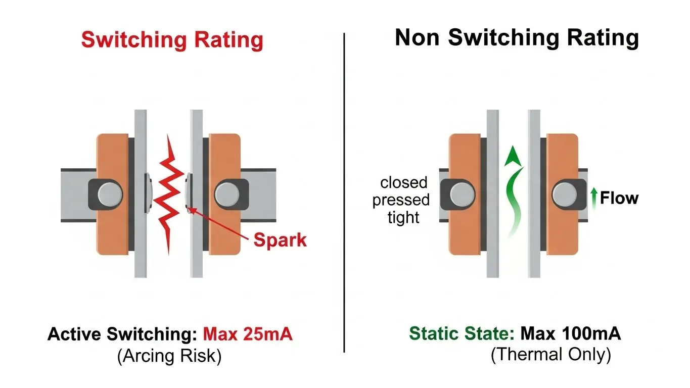
1. Switching Rating (The "Hot" Switch)
- Typical Spec: 25mA @ 24V DC
- Definition: This is the maximum current the switch can safely handle while the actuator is moving.
- The Physics: When you open a switch under load, a tiny electrical arc forms between the separating contacts. Even at 24V, this arc generates intense heat that pits the metal surface and carbonizes the plating. Since DIP switches have microscopic internal mass, they cannot absorb this heat. Exceeding 25mA during actuation destroys the contact surface instantly.
2. Non-Switching Rating (The "Cold" Switch)
- Typical Spec: 100mA @ 50V DC
- Definition: This is the maximum current the switch can carry while it remains stationary in the CLOSED position.
- The Physics: Once the contacts are physically locked together, there is no arcing risk. The limit is now determined purely by thermal rise (resistive heating). The contact mass can safely conduct 100mA without melting the plastic housing.
Engineer’s Takeaway: You can design a circuit that passes 100mA through a DIP switch, provided you guarantee the user never flips the switch while the device is powered on. If they do, the switch will likely fail open.
Voltage Ratings: Why 24V and 50V?
Most standard DIP switches are rated for low-voltage DC logic (3.3V, 5V, 12V, 24V). You will rarely see a DIP switch rated for 120V AC or 240V AC.
The DC Arcing Problem
DC voltage is harder to interrupt than AC voltage because DC never crosses zero. In an AC circuit, the arc extinguishes naturally 50 or 60 times a second. In a DC circuit, the arc is continuous. Given the tiny internal gap of a DIP switch (often <0.5mm), anything above 24V DC creates a high risk of sustained arcing during actuation.
For layouts involving higher voltages, spacing becomes critical to prevent dielectric breakdown. See our PCB Layout Tips for SMD DIP Switches for how to manage pad spacing effectively.
Minimum Ratings: The "Dry Circuit" Danger
Engineers obsess over the maximum rating, but in modern IoT devices, the minimum rating is the real killer.
If you are running a 3.3V microcontroller signal at 0.1mA (100µA), a standard tin-plated DIP switch might fail to conduct. This is known as the Dry Circuit problem.
- The Oxide Barrier: All non-noble metals (like Tin or Nickel) form a thin oxide layer instantly.
- Wetting Current: You need a specific amount of energy (voltage/current punch) to burn through this oxide layer.
- The Solution: For low-voltage logic (<5V, <10mA), you must use Gold-Plated contacts. Gold does not oxidize, ensuring a reliable connection even at micro-amp levels.
| Application | Voltage/Current | Recommended Contact Material |
| Microcontroller Input | 3.3V / 1mA | Gold (Essential) |
| LED Driver Signal | 5V / 10mA | Gold or Tin |
| Relay Coil / Fan | 24V / 50mA | Tin (Gold will wear off) |
Can I Use a DIP Switch to Drive an LED?
Yes, but do the math first.
A typical status LED draws 20mA. This is comfortably within the 25mA Switching Rating. However, if you are driving a bank of high-brightness LEDs drawing 50mA each, you are entering the "Non-Switching" zone.
- If you toggle that switch while the LEDs are on, you exceed the rating.
- Over time, this erodes the contacts, leading to high resistance.
For these applications, it is smarter to use the DIP switch to trigger a transistor (MOSFET) or logic gate, keeping the heavy load off the delicate switch contacts. This approach aligns with the principles in our Micro Switch Deep Dive, where separating control logic from power loads is best practice.
How Environmental Factors Derate Power
The ratings on the datasheet assume a room temperature of 25°C. In the real world, resistance rises with heat.
If your DIP switch is inside an enclosure that reaches 85°C, the maximum current carrying capacity drops. The internal resistance of the contacts (initially 50mΩ) will increase, generating more self-heating. If you combine high ambient heat with high humidity, oxidation accelerates.
For harsh environments, you should prioritize sealed switches. As explained in our guide on IP67 Waterproof Ratings, a sealed body prevents sulfur and moisture from attacking the contact interface, preserving the current handling capability over the switch's lifecycle.
Frequently Asked Questions
Immediate failure is unlikely, but you will cause microscopic pitting on the contacts. Over a few dozen cycles, the contact resistance will skyrocket from 50mΩ to several Ohms or Open Circuit, causing the signal to become unreliable.
The internal spacing (creepage and clearance) inside a standard DIP switch is too small to prevent arcing at mains voltage. It poses a fire and shock hazard. Use a rated rocker or toggle switch instead.
Gold is a soft metal. If you switch high currents (arcing) or apply high contact forces, the thin gold plating (often just 1-3 microns) can be vaporized or rubbed off, revealing the nickel/brass underneath. Gold is for signal precision; Tin is for power durability.
Indirectly, yes. Higher actuation force (contact pressure) lowers contact resistance, allowing slightly better current flow. However, you cannot change the force of a DIP switch; it is fixed by the design.
Momentary vs. latching tact switches are different beasts. While some larger latching switches can handle power, standard PCB tact and DIP switches are almost universally limited to logic-level signals (under 50mA).
Key Takeaways
- The Split Rating: Always distinguish between Switching (25mA) and Non-Switching (100mA) capacity.
- Safety Protocol: Never actuate a DIP switch while the device is powered if the load exceeds 25mA.
- Gold vs. Tin: Use Gold for logic (3.3V/5V) to prevent oxidation; use Tin for higher currents (24V) to withstand arcing.
- Logic Only: DIP switches are configuration devices, not power disconnects. Use them to drive gates, not motors.
Conclusion
Understanding DIP switch current and voltage ratings is about respecting the component's purpose. It is a precision configuration tool, not a power interrupter. By keeping your "hot switching" currents under 25mA and selecting the right plating material for your voltage level, you ensure your device remains configurable for years without contact failure.
If you are designing a new board, always verify if the user might accidentally toggle the switch while the unit is live. If that risk exists, design your circuit to stay within the lower "Switching" limit.