


DIP Switch Basics for New Engineers
DIP switches are manual electric switches packaged in a standard "Dual In-line Package" used to configure hardware behavior without software intervention. For new engineers, they are the standard method for setting device addresses, baud rates, or boot modes on a PCB.
Unlike a momentary button used for typing, a DIP switch is a "set-and-forget" component. It provides a non-volatile, visual indication of a device's setting that persists even when power is lost. Whether you are designing a garage door opener or an industrial sensor network, mastering these components is a rite of passage for embedded systems design.
Why Use Physical Switches in a Software World?
In an era of Wi-Fi configs and Bluetooth pairing, you might ask: Why do we still use physical switches?
- Reliability: A physical switch doesn't forget its setting if the EEPROM gets corrupted.
- Security: You cannot "hack" a DIP switch remotely; someone must physically be at the device to change the address.
- Diagnostics: A field technician can walk up to a machine and immediately see its configuration (e.g., "Address 5") without needing a laptop or diagnostic tool.
For a broader look at how these switches fit into the ecosystem of electromechanical components, check out our guide on What Beginners Should Know About PCB Switches.
Types of DIP Switches: More Than Just Sliders
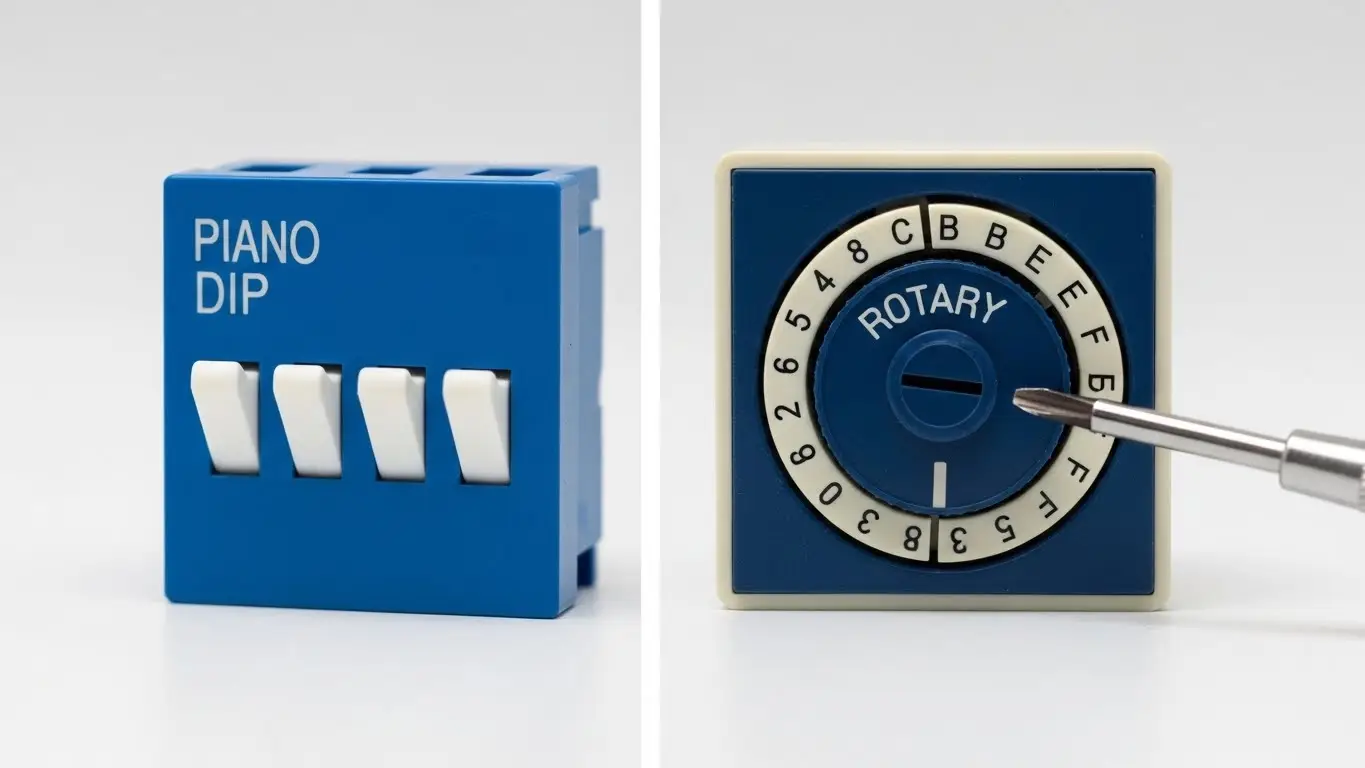
While the "Piano" style is famous, there are other types optimized for different engineering constraints.
1. Slide and Rocker (The Standard)
These are simple SPST (Single Pole Single Throw) switches.
- Slide: Standard toggle action.
- Rocker: Pivots like a seesaw. Harder to accidentally bump than slide switches.
- Best for: Simple On/Off settings.
2. Rotary DIP Switches (The Encoder Style)
These look like dials with numbers (0-9 or 0-F). Internally, turning the dial closes a specific combination of contacts to output a BCD (Binary Coded Decimal) or Hexadecimal code.
- Best for: Setting device IDs where "Dialing to 7" is more intuitive for the user than calculating binary "0111".
The Circuit: Pull-Up Resistors are Mandatory
One of the most common mistakes junior engineers make is connecting a DIP switch directly between a microcontroller pin and Ground, assuming "Open" means "Off."
It does not. An open switch leaves the pin "floating," creating random noise. You must use a Pull-Up Resistor to force the pin to a Logic High (1) when the switch is open.
- Switch Open: Resistor pulls pin to VCC (Logic 1).
- Switch Closed: Direct connection to GND (Logic 0).
Pro-Tip: Instead of soldering 8 individual resistors for an 8-position DIP switch, use a SIP (Single In-line Package) Resistor Network. It contains 8 resistors in one package, saving massive amounts of board space.
Need a refresher on why this logic is inverted (Active Low)? Read our deep dive on How Switches Control Logic Levels.
Decoding the Binary: How to Read the Switch
The primary function of a DIP switch is to set a number. This works on binary logic ($2^n$).
Imagine an 8-position switch. Each switch represents a mathematical value:
| Switch Position | Binary Value | Value if ON |
| 1 (LSB) | $2^0$ | 1 |
| 2 | $2^1$ | 2 |
| 3 | $2^2$ | 4 |
| 4 | $2^3$ | 8 |
| ... | ... | ... |
| 8 (MSB) | $2^7$ | 128 |
Example: To set "Address 5", you turn ON switches 1 ($1$) and 3 ($4$).
$1 + 4 = 5$.
The Engineering Trap (LSB vs. MSB):
Always check the datasheet. Does Switch 1 represent the Least Significant Bit (1) or the Most Significant Bit (128)? Getting this backwards is the #1 reason for configuration errors in the field.
For more practice on setting these codes, refer to our specific How DIP Switches Are Used in Basic Electronics guide.
Troubleshooting: When the Code Doesn't Match
You set the switches to "5," but the microcontroller reads "7." What went wrong?
- Oxidation: If the device is old, the contacts inside the switch might be oxidized, preventing current flow even when closed.
- Solder Flux: If the switch wasn't taped/sealed during the soldering process, flux might have wicked inside, insulating the contacts.
- Active High Confusion: Did you write your code expecting "On" to be "1"? Remember, with pull-ups, "On" usually means Ground (0).
If you suspect the switch itself is broken, don't guess. Use a multimeter to verify continuity. We cover the exact steps in The Simplest Way to Test a Tact Switch (the continuity test applies to DIP switches too).
Environment and Durability
If you are designing for a clean server room, a standard open DIP switch is fine. But if this PCB is going into a humid greenhouse or a vibrating machine, you need:
- Sealed/Tape Sealed Switches: To prevent moisture ingress.
- Gold Contacts: For better corrosion resistance on low-voltage signals.
For high-stakes environments, explore our Industrial Switches Comprehensive Guide to choose the right ingress protection.
Frequently Asked Questions
DIP (Dual In-line Package) has two parallel rows of pins. SIP (Single In-line Package) has one row. DIP is mechanically more stable and industry standard; SIP is used only when horizontal board space is extremely tight.
It depends on the firmware. Most devices only read the DIP switch state during "boot up." If you change it while powered, nothing happens until you restart the device.
DIP switches are symmetrical components. If the PCB designer installed the footprint "upside down" relative to the text on the board, the numbers will be inverted. Always follow the "ON" arrow, not the text orientation.
Generally, no. Since DIP switches are read once at startup (static), switch bounce isn't usually an issue. However, if you are using a DIP switch as a dynamic input (like a toggle), you might need to treat it like a Tactile Switch in Microcontroller Projects.
Key Takeaways
- Use Resistors: Never leave a DIP switch input floating; use Pull-Up resistors (or SIP networks) to ensure stable Logic 1s.
- Check Orientation: Verify which switch is the LSB (1) and which is the MSB (128) before coding.
- Calculate Binary: Use the $2^n$ addition method to determine your target address.
- Seal It: For harsh environments, use tape-sealed switches to prevent contact failure.
Conclusion
DIP switches bridge the gap between physical hardware and digital configuration. They are simple, robust, and essential for reliable engineering. By understanding the binary logic and proper electrical termination, you ensure your device knows exactly what it's supposed to do the moment it powers up.