Debouncing Issues in DIP & Tact Switches: The Engineering Guide
Understanding debouncing issues in DIP and tact switches is the difference between a reliable device and a glitchy prototype. When mechanical contacts close, they don't just connect; they bounce microscopically, creating "phantom" signals that microcontrollers misinterpret as multiple inputs. This guide covers the physics of contact bounce and the hardware and software solutions to fix it.
What Exactly Is Switch Bounce?
Switch bounce (or contact chatter) is a transient mechanical phenomenon where metal contacts separate and reconnect rapidly before settling into a stable state.
When you press a button, you are slamming two pieces of metal together. In the microscopic world, this is a chaotic event. The elastic energy in the materials causes them to rebound multiple times—like a tennis ball dropped on concrete—before gravity and friction bring them to a halt.
For a human, this happens instantly. But for a microcontroller running at 16MHz, a 5-millisecond bounce event is an eternity. The processor sees a rapid-fire stream of HIGH-LOW-HIGH-LOW signals, often registering 10 to 50 clicks for a single physical press.
Engineer's Note: In my years of debugging IoT devices, the "double-click" bug is almost never a software logic error. It is almost always a failure to account for the physics of the switch mechanism. I’ve seen brand new prototypes fail QA simply because the debounce delay was set to 5ms, but the specific switch batch had a natural bounce of 8ms.
Why Do DIP and Tact Switches Bounce Differently?
DIP and tact switches bounce differently because their internal mechanisms release potential energy in distinct ways. Tact switches use a high-velocity snap-action dome, creating sharp spikes, while DIP switches use a sliding contact that generates "scratchy" noise.
Let's break down the mechanics:
Tactile Switches (Snap Action)
As we discussed in our guide on factors affecting tact switch tactile feel, tactile switches rely on a bistable metal dome.
- The Physics: You apply force until the dome collapses. This collapse is instantaneous (snap-action).
- The Bounce: The high velocity of the dome hitting the PCB pads creates a significant impact shock. This results in high-amplitude bounce spikes, usually lasting 2ms to 10ms.
- Travel Factor: A longer tact switch travel distance can allow the actuator to build more momentum, potentially increasing the initial impact force and bounce duration.
DIP Switches (Sliding Action)
DIP switches typically use a sliding wiper mechanism.
- The Physics: The actuator pushes a metal wiper across a stationary contact.
- The Bounce: This is less of a "bounce" and more of a "stutter." Surface roughness or oxidation can cause intermittent contact as the wiper transitions.
- The Risk: Sliding contacts are prone to "make-break" noise if the contact pressure is uneven. Using gold-plated contacts significantly reduces this noise by providing a smoother, oxide-free surface.
How Long Does Switch Bounce Last?
Switch bounce typically lasts between 2ms and 20ms, depending on the switch age, actuation force, and material quality.
While a fresh switch might settle in 5ms, an aged switch can bounce for much longer.
| Switch Age | Typical Bounce Duration | Cause of Increase |
| New (0 Cycles) | < 5ms | Pristine spring tension. |
| Mid-Life (100k Cycles) | 5ms - 10ms | Slight relaxation of the dome. |
| End of Life (>1M Cycles) | > 20ms | Metal fatigue and surface pitting. |
Critical Insight: Never design your software debouncing based on a brand-new switch. You must account for the "Aging Bounce." As described in our tact switch lifecycle ratings explained, as the metal dome fatigues, it loses its snap crispness. This "mushy" action often results in a lazy, rattling closure that confuses standard debounce algorithms.
Hardware Debouncing: The RC Filter Solution
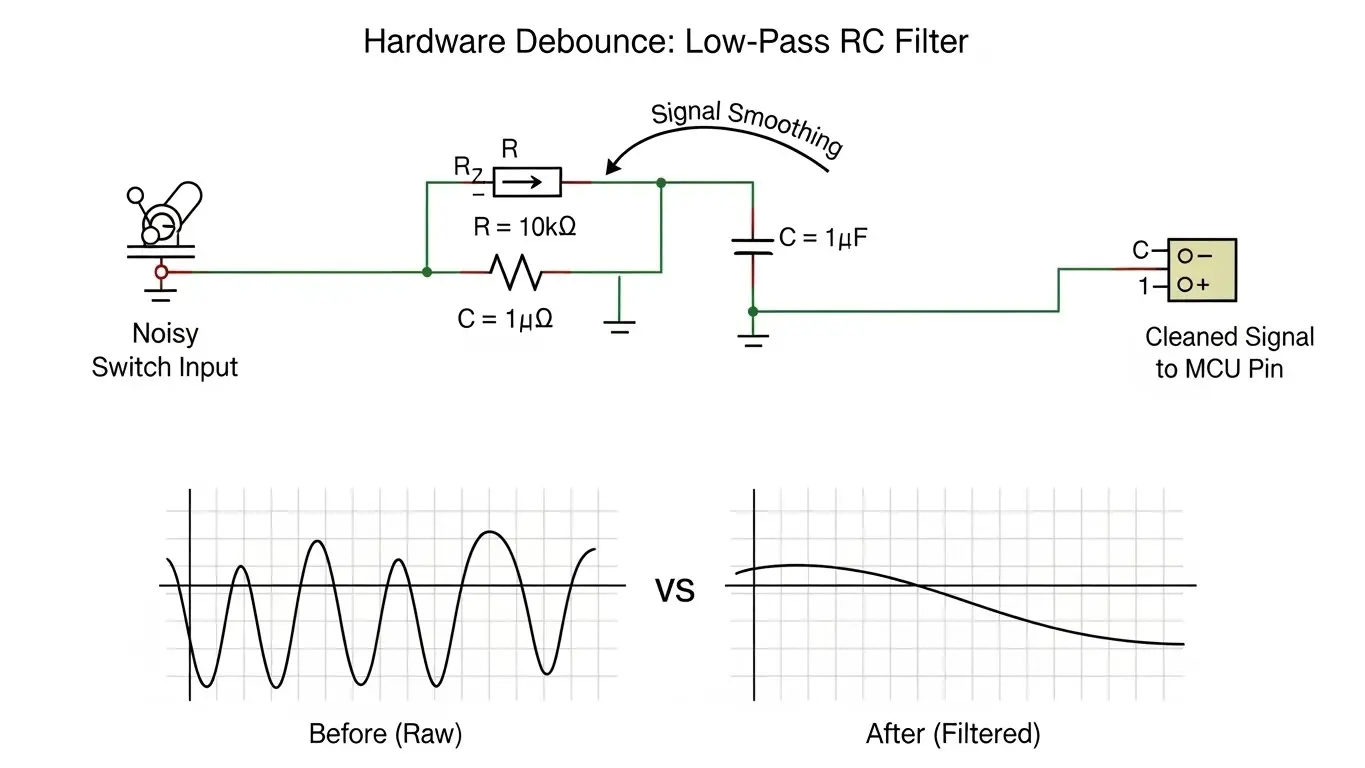
Hardware debouncing uses a capacitor to absorb voltage spikes and a resistor to limit current, smoothing the noisy signal into a clean curve.
This is the "set it and forget it" method. By conditioning the signal before it reaches the microcontroller, you save CPU cycles and code complexity.
How to Calculate the RC Filter
The most common circuit is a low-pass RC filter.
- Resistor (R): Limits the current.
- Capacitor (C): Stores charge to resist rapid voltage changes.
The Time Constant ($\tau$) is calculated as $\tau = R \times C$.
- Target: You generally want a time constant around 10ms to 20ms to cover the worst-case bounce.
- Typical Values: A 10kΩ resistor and a 1µF capacitor give a 10ms constant ($10,000 \times 0.000001 = 0.01s$).
Warning: When designing yourPCB layout tips for SMD DIP switches, place these capacitors as close to the microcontroller input pin as possible to filter out RF noise as well.
Software Debouncing: The Logic Approach
Software debouncing involves programming the microcontroller to ignore signal changes for a set period (usually 20ms) after the initial trigger.
This is cost-effective as it requires no extra components, but it consumes processor resources.
The "Wait and See" Algorithm
This is the simplest method for non-critical buttons.
- Detect: Interrupt or loop sees pin go LOW.
- Wait: Code pauses or sets a timer for 20ms.
- Check: Code reads the pin again.
- Confirm: If pin is still LOW, register the press. If HIGH, ignore as noise.
The "Continuous Sampling" Algorithm
For high-reliability applications, you use a counter.
- Check the switch state every 1ms.
- Increment a counter if the state is stable.
- Reset the counter if the state changes.
- Register a press only when the counter reaches 20 (i.e., 20ms of stability).
Does Voltage Affect Debouncing?
Yes, low voltage levels (3.3V or 1.8V) are more susceptible to "noise" that mimics bounce, known as the dry circuit problem.
In high-voltage circuits (like 24V), the electricity can arc across microscopic gaps, effectively cleaning the contact. In low-voltage logic circuits, the signal might struggle to punch through surface oxidation.
- The Symptom: The switch reads as "flickering" even when pressed firmly.
- The Fix: This isn't strictly a bounce issue; it's a contact resistance issue. Ensure you follow our DIP switch current & voltage rating guide and use gold-plated contacts for low-power logic to ensure a clean signal make.
Debouncing Latching vs. Momentary Switches
Latching switches still require debouncing because the internal locking mechanism involves the same metal-on-metal impact as momentary switches.
A common misconception is that momentary vs. latching tact switches behave differently regarding signal noise. While a latching switch holds the state mechanically, the transition to that state is just as chaotic.
- Momentary: Bounces on Press (Make) and Release (Break).
- Latching: Bounces on Press-to-Lock and Press-to-Unlock.
In fact, latching switches can sometimes have more noise during the release phase because the spring mechanism snaps the contact open violently.
Common Mistakes in Debounce Design
Even experienced engineers trip up on these nuances.
- Ignoring the Interrupt Problem: If you hook a noisy switch directly to an Interrupt Service Routine (ISR) without hardware filtering, your CPU will crash. The interrupt will fire 50 times in 1ms, freezing the main loop. Always use RC filters with interrupts.
- Blocking Delays: Using
delay(20)in your code freezes the entire device. Users hate lag. Use non-blocking timers (likemillis()in Arduino or hardware timers). - Forgetting Environmentals: As discussed in our micro switch deep dive, cold temperatures stiffen metal and rubber. A switch that bounces for 5ms at 25°C might bounce for 15ms at -10°C.
Conclusion
Mastering debouncing issues in DIP and tact switches requires a holistic approach. You cannot rely solely on the datasheet's "typical" bounce spec. You must engineer for the worst-case scenario—an aging switch in a cold environment.
Whether you choose a hardware RC filter for bulletproof reliability or a smart software algorithm for cost savings, the goal is the same: masking the chaos of physics to provide a clean, singular digital truth.
Frequently Asked Questions (FAQ)
For most applications, 20ms is the "Golden Number." It is long enough to cover the bounce of an aging switch but short enough that the user doesn't perceive lag (human reaction time is roughly 100ms).
No. You need a resistor to limit the current. Connecting a capacitor directly across a switch can cause a massive current spike when the switch closes (shorting the capacitor), which can weld the contacts together or damage the switch.
Yes, slightly. As detailed in our how IP67 waterproof rating works for tact switches, the silicone seals act as dampers. They absorb some of the kinetic energy of the actuator, potentially reducing the settling time of the contact dome.
If a DIP switch flickers without being touched, it's likely a "floating pin." Ensure you have a pull-up or pull-down resistor enabled. If it flickers during adjustment, it is contact bounce or oxidation—cleaning the contacts or slowing down the read speed in software will help.
A Schmitt Trigger is a specific hardware chip that adds hysteresis. It cleans up the analog "curve" of an RC filter into a sharp, digital square wave. It is the gold standard for hardware debouncing in noisy industrial environments.