Advanced Troubleshooting & Repair
In industrial automation, network downtime is measured not in minutes, but in lost revenue and production stalls. The industrial Ethernet switch is the backbone of this infrastructure, connecting PLCs, SCADA systems, and HMIs. When it fails, the priority is immediate isolation and resolution.
At HX Switch, we understand that "turning it off and on again" is rarely a sufficient solution for complex manufacturing environments. Ruggedized equipment faces unique challenges—from electromagnetic interference (EMI) to extreme thermal fluctuations—that office-grade hardware never encounters.
This guide provides a systematic, engineer-level approach to diagnosing and repairing industrial network faults, moving beyond basic checks to advanced hardware and logic analysis.
The Diagnostic Workflow: Layer 1 to Layer 3
Effective troubleshooting requires a logical structure. In high-pressure situations, it is easy to jump straight to checking software configurations, but our internal data suggests that over 70% of network failures originate at the physical layer (Layer 1).
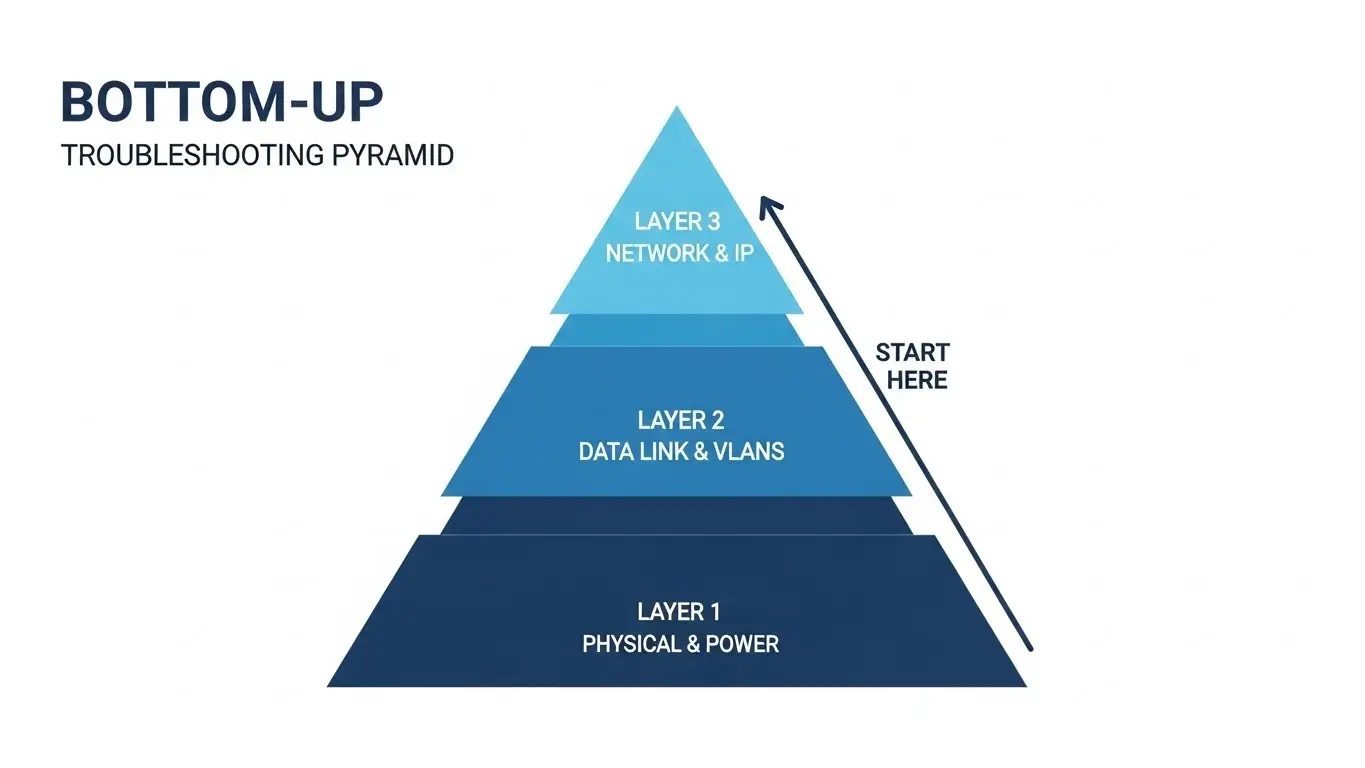
We recommend a "Bottom-Up" diagnostic approach tailored for industrial cabinets:
- Layer 1 (Physical): Power inputs, cabling integrity, port physical status, and environmental conditions.
- Layer 2 (Data Link): MAC address tables, VLAN tags, Spanning Tree Protocol (STP) status, and negotiation speeds.
- Layer 3 (Network): IP configurations, routing protocols, and gateway accessibility (for Layer 3 switches).
By validating the physical infrastructure first, you avoid spending hours debugging a VLAN configuration when the root cause is actually a voltage drop on a 24V DC power rail.
Physical Hardware & Environmental Diagnostics
Industrial switches often reside in unconditioned environments. Before assuming a software bug, inspect the hardware for environmental stress factors.
Power Supply Stability
Unlike office switches using standard AC plugs, industrial units often rely on 12-48V DC inputs via terminal blocks.
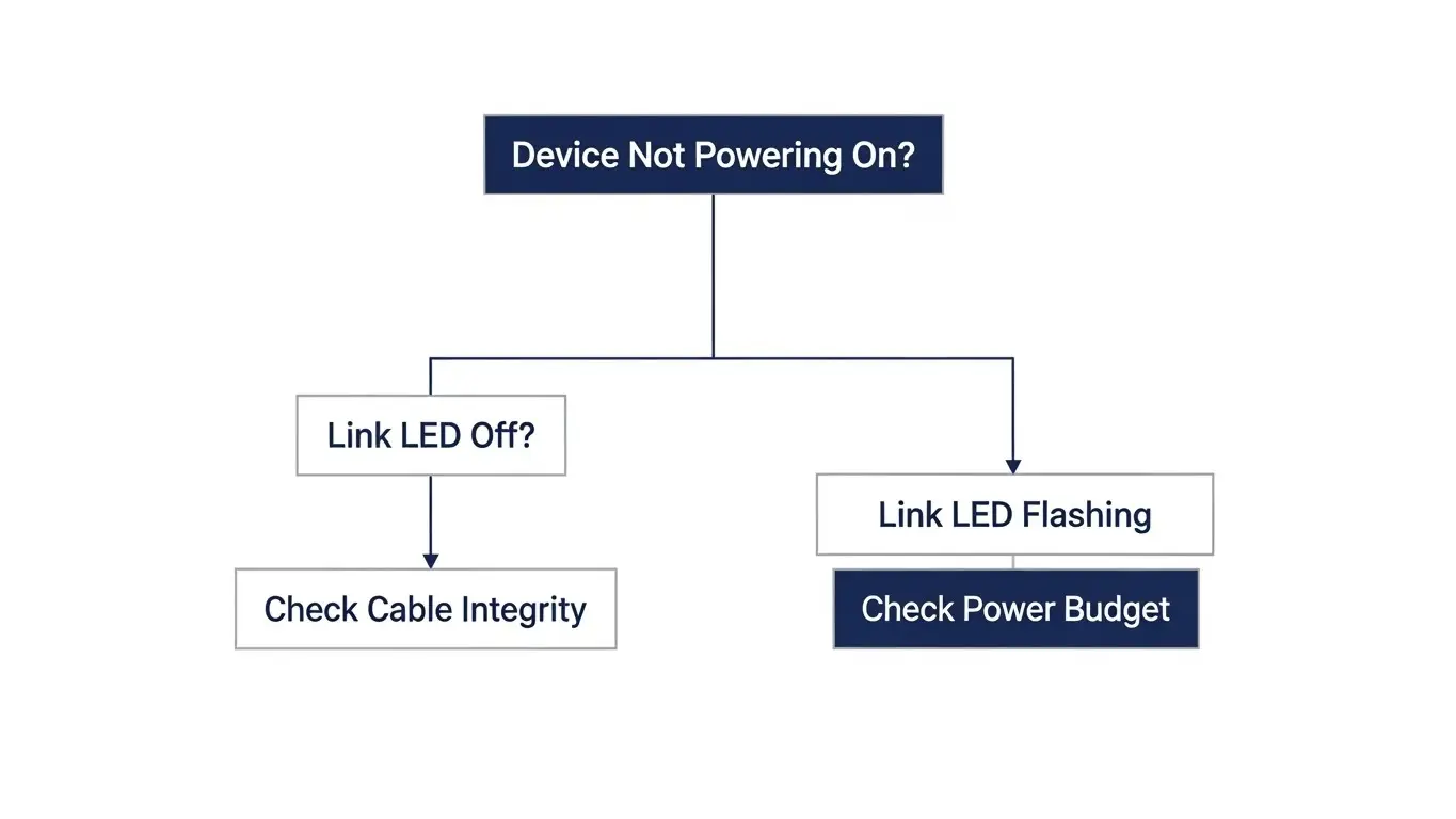
- Voltage Sag: Use a multimeter to verify the input voltage under load. A power supply dipping below the threshold (e.g., <10V on a 12V input) can cause random reboots or packet drops without fully powering down the unit.
- Redundancy Failure: If the switch supports dual power inputs (PWR1 and PWR2), verify that both are active. A failure in the primary supply might be masked by the secondary, leaving the system vulnerable to a total blackout.
Port & Cable Physicality
- Connector Stress: In high-vibration environments, RJ45 connectors can suffer from fretting corrosion (micro-movements wearing down contact plating). Inspect ports for bent pins or debris.
- Fiber Optics: For SFP modules, check for dust contamination. A single speck of dust on a fiber core can cause significant dB loss, leading to intermittent link errors that look like software faults.
Environmental Limits
Check the unit’s operating temperature. If a switch exceeds its rated thermal limit (often -40°C to 75°C for our industrial lines), it may enter a thermal protection mode, shutting down non-essential ports or throttling performance. Ensure DIN-rail spacing is sufficient for passive airflow.
Resolving Layer 2 Connectivity & Configuration Faults
Once hardware integrity is confirmed, the focus shifts to how data moves through the switch.
The Network Loop (Broadcast Storms)
One of the most common causes of a total network freeze is a loop. In unmanaged switches without loop protection, a single cable plugged into two ports on the same switch will bring down the entire segment.
- Symptoms: All port LEDs flashing synchronously at high speed; high latency; unresponsive management interface.
- Resolution: Disconnect redundant links one by one until traffic normalizes. For managed switches, ensure RSTP (Rapid Spanning Tree Protocol) is enabled and effectively blocking redundant paths.
VLAN Mismatches
In industrial protocols like PROFINET or EtherNet/IP, traffic prioritization often relies on VLAN tagging (802.1Q).
- The Issue: A common misconfiguration occurs when a device sends tagged frames (e.g., VLAN 10) to a switch port configured as "Access" (expecting untagged traffic), or vice versa.
- Diagnosis: If the link light is solid but data isn't passing, verify the port's VLAN membership. Ensure the PVID matches the connected device's requirements.
Link Flapping
"Flapping" describes a port that rapidly alternates between "Up" and "Down" states. This is frequently caused by a speed/duplex mismatch. If a legacy PLC is fixed at 10Mbps/Half-Duplex and the switch is set to Auto-Negotiate, the link may fail to stabilize. Hard-coding the speed and duplex settings on the switch port often resolves this.
Deep Dive: Power over Ethernet (PoE) Failure Mode
PoE adds complexity to troubleshooting because the switch acts as a power source. Failures here are often distinct from data transmission issues.
The Power Budget Trap
Every PoE switch has a maximum total power budget (e.g., 240W).
- The Scenario: You connect four PTZ cameras (30W each) and the switch works. You add a fifth, and random cameras start rebooting.
- The Cause: You have exceeded the global power budget. The switch will prioritize ports based on priority settings (usually low port numbers first) and cut power to others.
- The Fix: Calculate the total wattage of all Powered Devices (PDs) and ensure it stays within 80-90% of the switch's total budget.
Cabling Distance and Resistance
IEEE standards (802.3af/at/bt) specify a maximum distance of 100 meters. However, in industrial settings using stranded patch cables or poor-quality CCA (Copper Clad Aluminum) wire, resistance is higher. Voltage drop over long runs can result in the PD receiving less than the required voltage, preventing it from powering up despite a "Good" link status.
| Symptom | Probable Cause | Corrective Action |
| Port LED Blinking Amber | Short Circuit or Overload | Check cable integrity & PD Class |
| Device Power Cycles | Exceeded Power Budget | Check Total Wattage vs. Switch Max |
| No Power, Data OK | PoE Mode Mismatch | Verify Mode A vs Mode B compatibility |
Analyzing Traffic & Logs (The Digital Multimeter)
Modern managed industrial switches provide built-in diagnostic tools that serve as digital multimeters for your data.
Port Mirroring
To diagnose complex protocol failures without disrupting production, use Port Mirroring. This copies all traffic from a source port (connected to the PLC) to a destination port (connected to a laptop with Wireshark). This allows you to inspect packet headers for checksum errors, retransmissions, or malformed PROFINET frames.
Interpreting Syslogs
The system log is the first place to look for historical context. Key entries to watch for include:
- Cold Start: Indicates the switch lost power and rebooted (check power supply).
- Topology Change: Indicates STP detected a network change (check for loose cables or failing links).
- Fan Failure: Precursor to overheating.
When to Repair vs. When to Replace
Not all failures are serviceable in the field. Understanding the distinction saves time and protects network integrity.
Field Repairable
- Firmware Corruption: Often recoverable via a TFTP boot or console cable serial connection.
- Fan Modules: On modular switches, fans are consumable components and can be swapped.
- Configuration Errors: Always reversible via a factory reset.
Requires RMA / Replacement
- Fried ASICs: If a group of ports is dead (no link light with known good cable) after a lightning strike or power surge, the internal switching chip is likely damaged.
- Internal Component Failure: Bulging capacitors or the smell of ozone/burnt electronics indicates board-level failure.
- Corrosion: Extensive oxidation on the motherboard due to moisture ingress cannot be reliably cleaned; the unit must be replaced to ensure future reliability.
Conclusion
Advanced troubleshooting is about isolating variables. By methodically verifying the physical installation, power delivery, and logical configuration, engineering teams can resolve 90% of industrial network faults without external support.
However, reliability begins with the hardware itself. Ensuring your network is built on switches designed for the rigors of the industrial environment—like those engineered by HX Switch—minimizes the frequency of these repairs.
Frequently Asked Questions
In an unmanaged switch, look for all port LEDs flashing rapidly and synchronously. Network traffic will likely halt completely. To identify the loop, disconnect cables one at a time until the blinking pattern returns to normal activity.
This is usually caused by exceeding the switch's total power budget. If the connected devices draw more power than the switch can supply, it will cut power to lower-priority ports or reboot to protect its internal circuitry.
Rarely. While firmware can improve buffer management, packet loss is more often caused by cabling faults, duplex mismatches, or electromagnetic interference (EMI). Firmware should be updated, but physical checks should come first.
Visually inspect the pins for bending or corrosion. Functionally, plug a known working device with a known good cable into the suspect port. If the link LED does not light up, or if it lights up but drops packets while moving the cable head, the physical port is likely damaged.
"Link Down" means there is no connection detected at all. "Link Flapping" means the connection is established and then lost repeatedly (e.g., every few seconds). Flapping typically indicates a bad cable, a speed mismatch, or a failing port negotiation.